Gearbox & Transmission
Gearshift & modifications
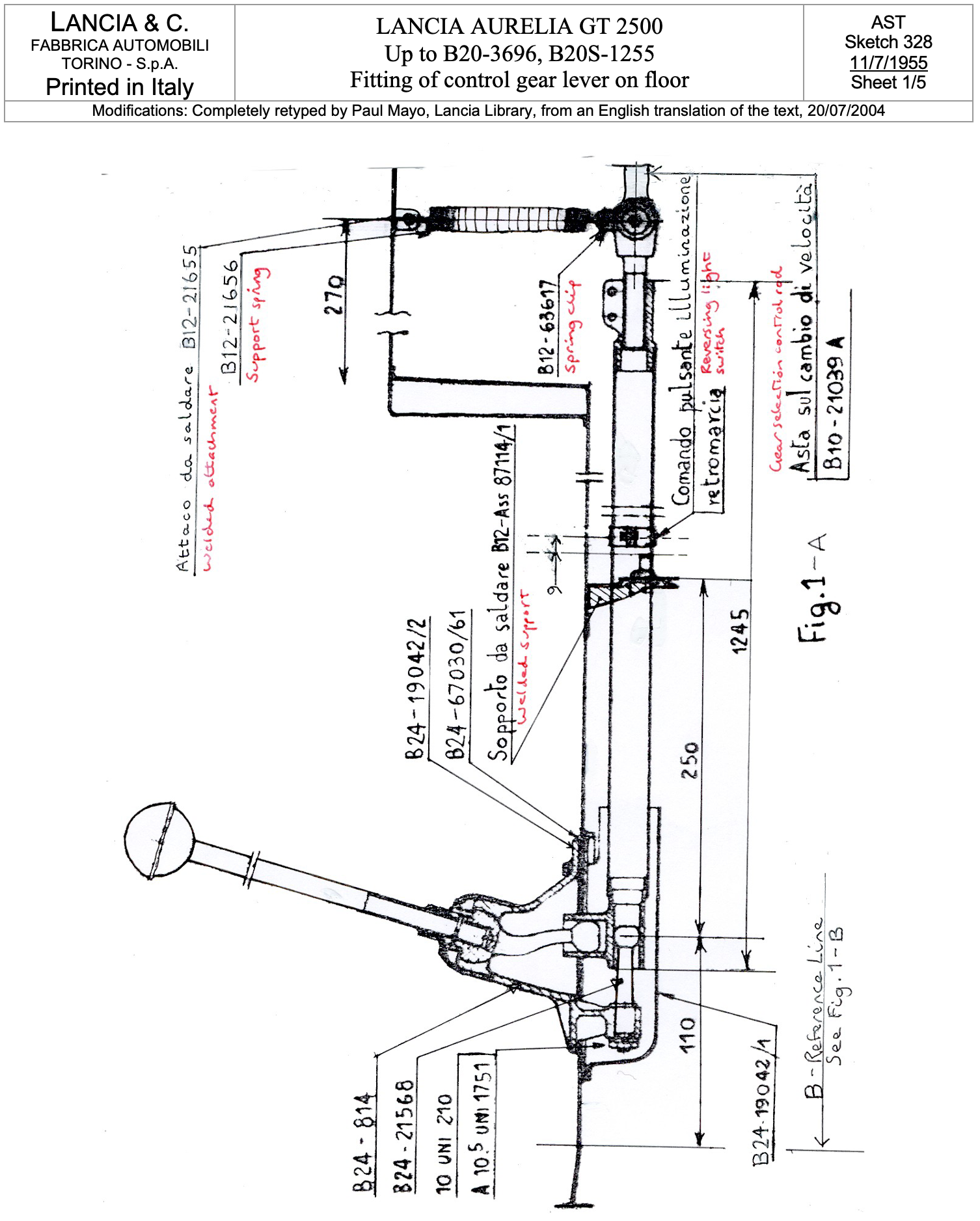
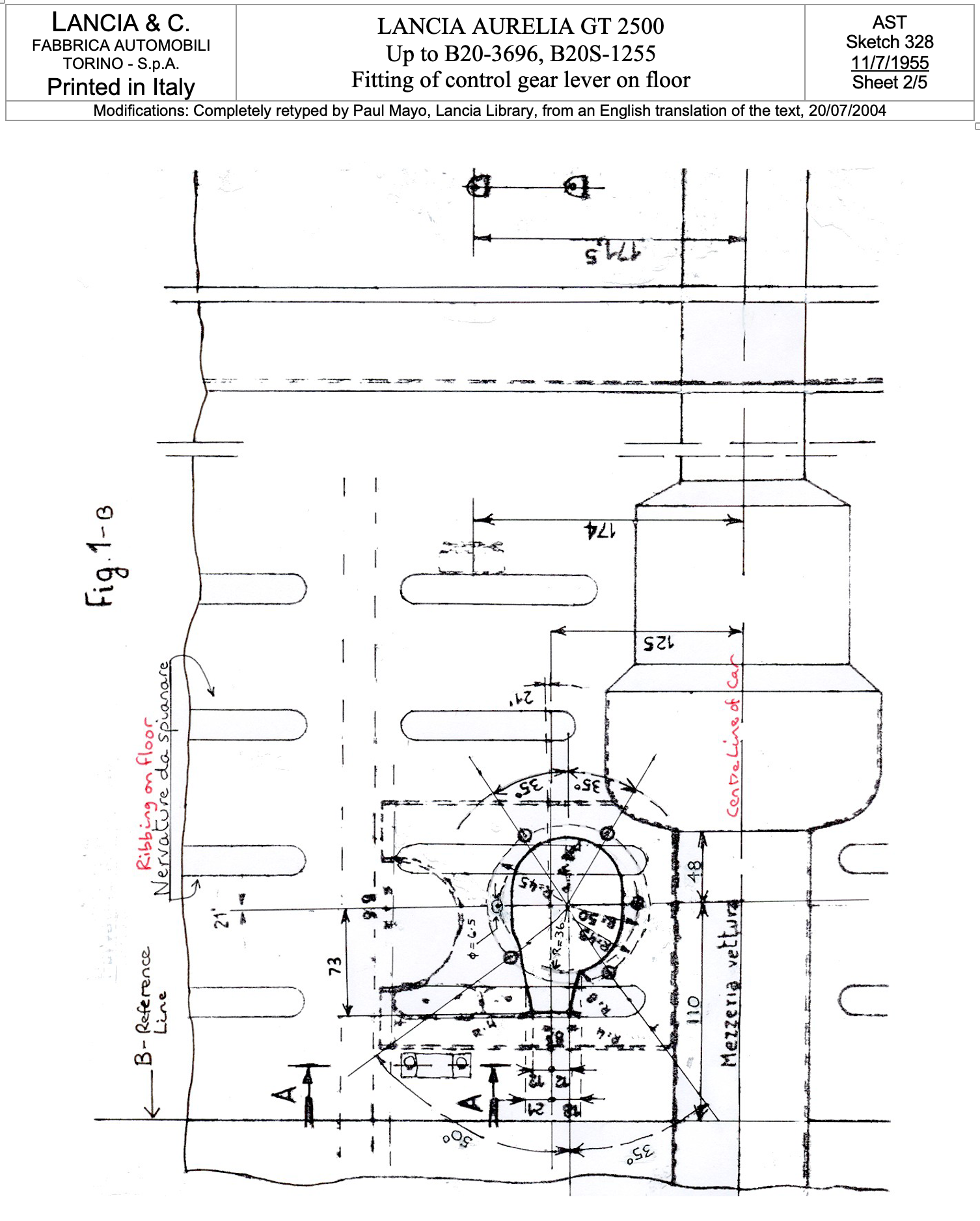
The Aurelia was initially supplied with a very good column gearshift which was widely admired for its precision in comparison with other marques at that time. Many cars were modified to a floor shift & there was both a Lancia Factory & a Nardi conversion kit. The Sketches below show the response of the factory to this demand.
Series I Gear Shifts [Tav. 27 SI & Tav. 27 bis SI]
Two types were fitted as follows

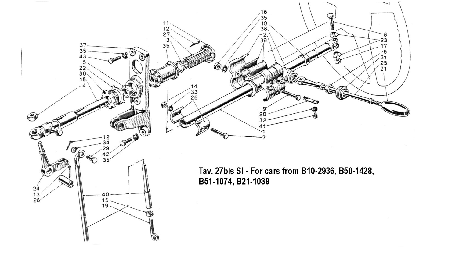

B12 & B20 Series 4 Cars - Column Gear Change

Series II B12 & B20/B24 Cars – Column Gear Change
Positions of Column Gear Change Lever
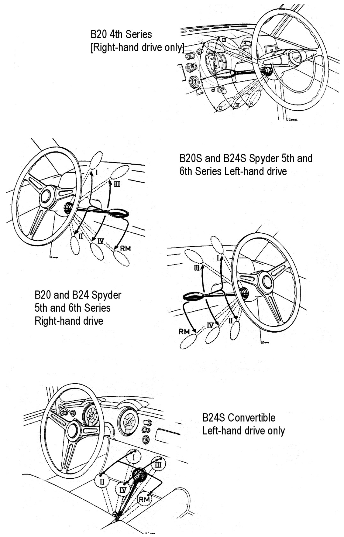
Series II B12 & B20/B24 Cars – Column Gear Change

Series II B20/B24 Series 5 & 6 Cars – Column Gear Change

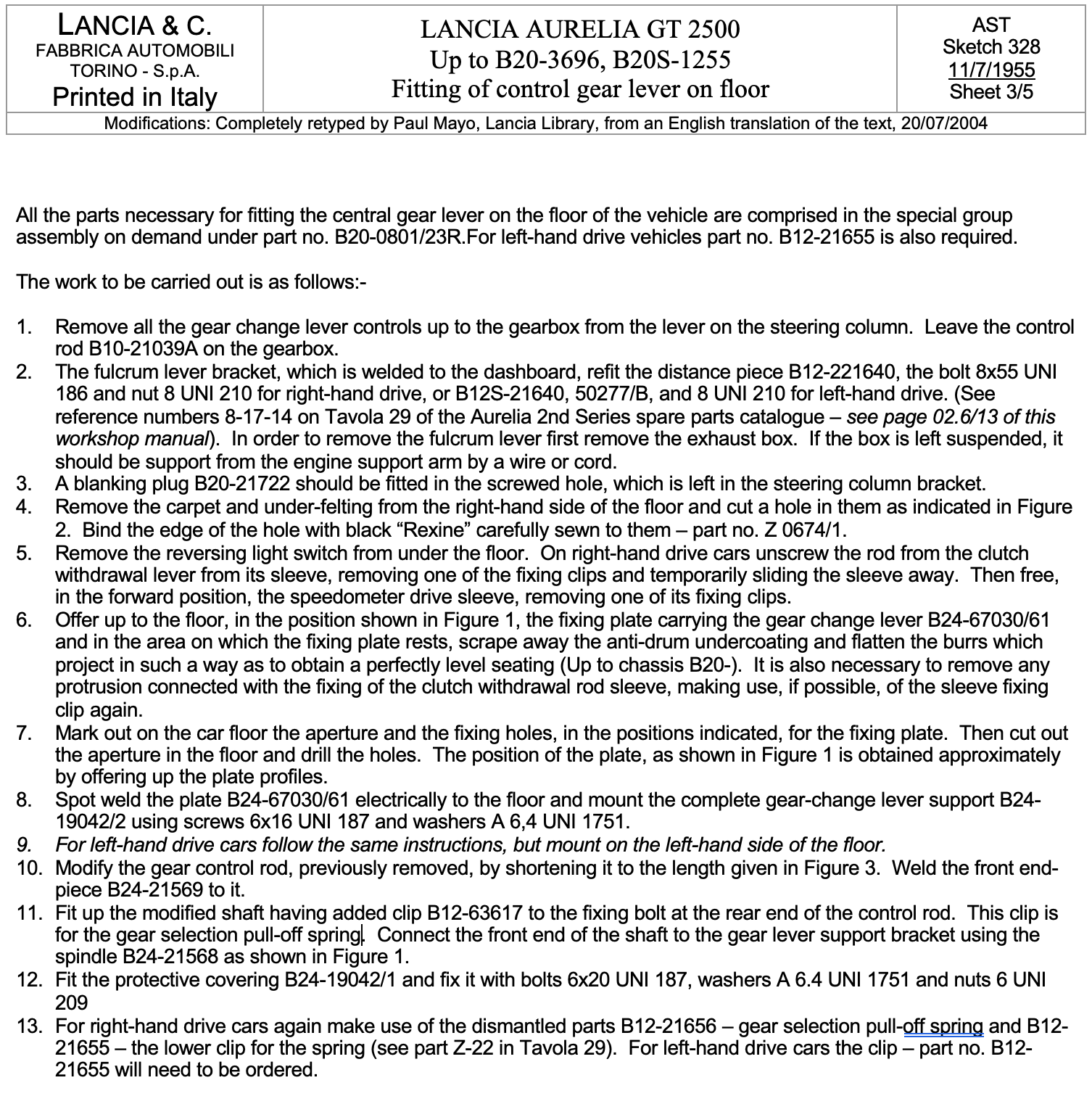
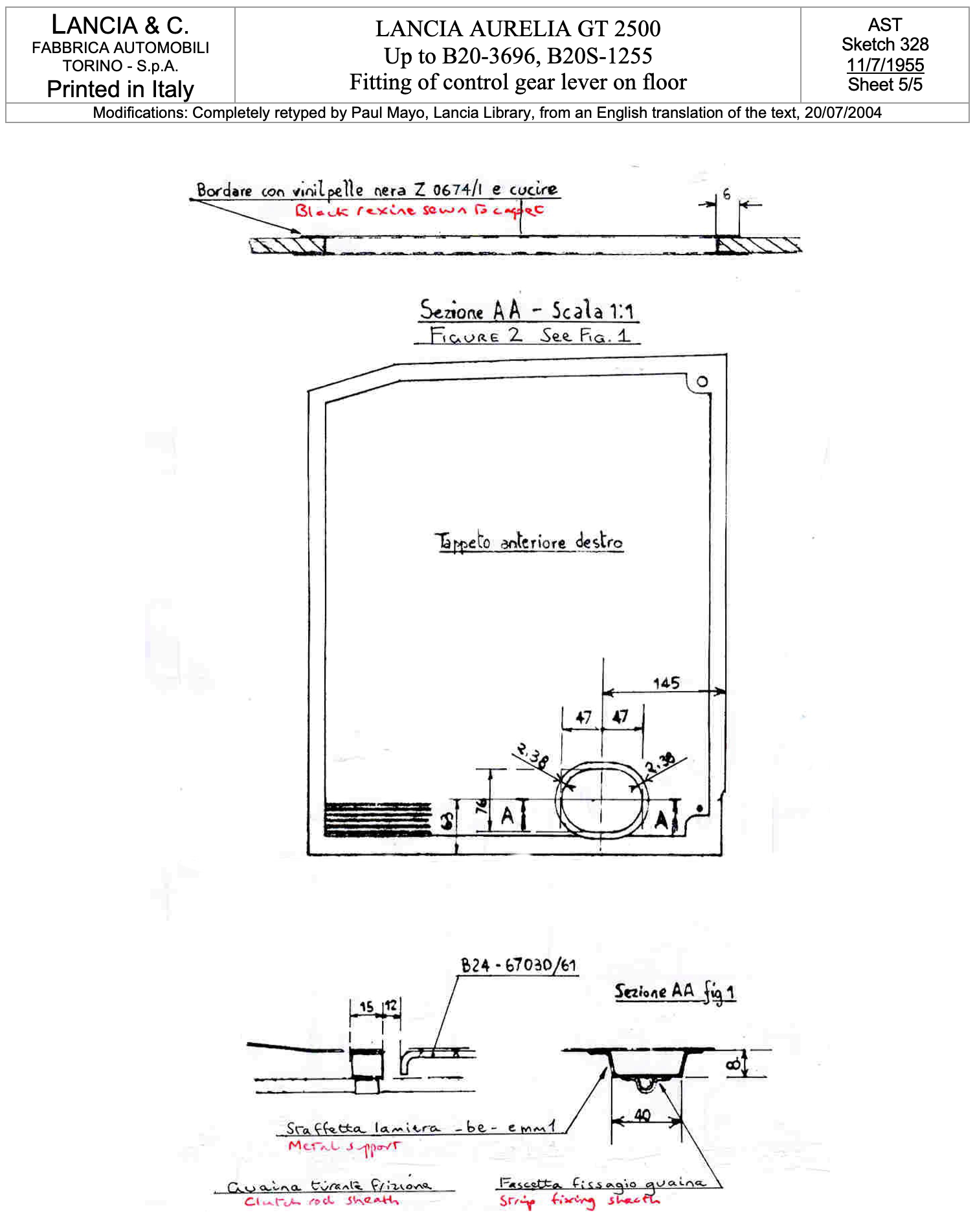
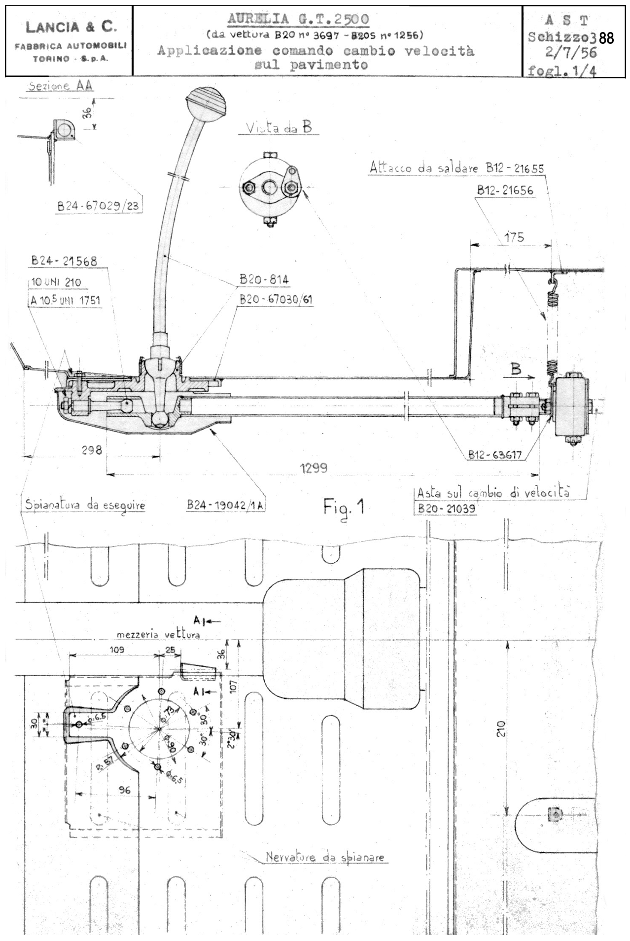
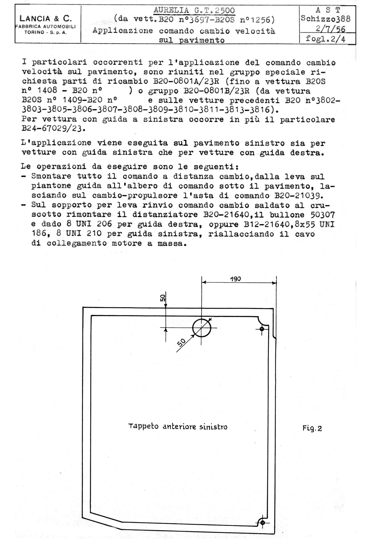
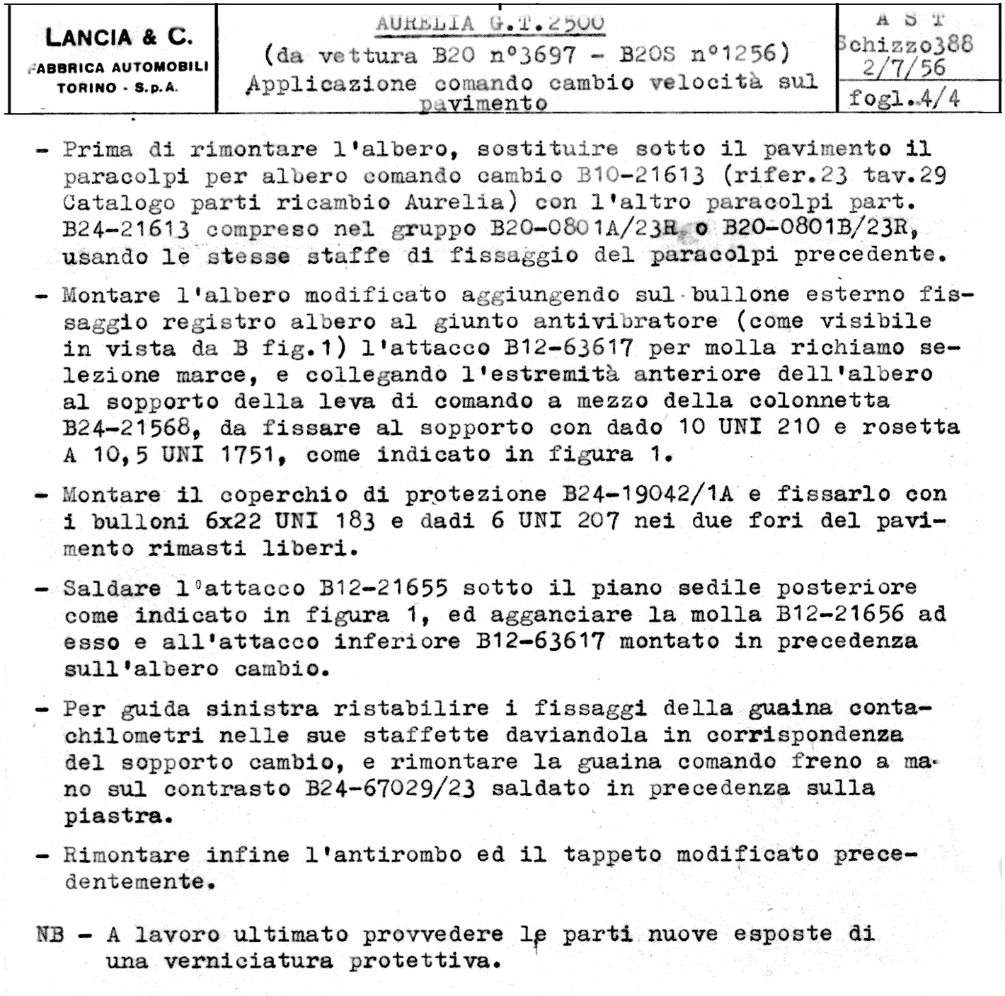
Series II B20 Cars – Floor Gear Change


Gearbox Mountings, Gearbox Removal & Replacement

Description, Disassembly, Overhaul & Reassembly of the Aurelia Rear End Assembly
1st Type as used on B10, B221, B22, B20 Series 1 to 4 & B24 Series 4
by Clive Beattie (dec’d) [Ref. 9]
Description
All these cars were equipped with the same type of rear end, clutch, gearbox, differential & brakes as a complete assembly. Alloy is used throughout for all housings, cover plates, speedo. drive, some brake shoes & oil pump housing. Synchromesh on 2nd, 3rd& 4th speed, all at excellent ratios, is fitted with a slight overdrive in the 4th speed ratio.
The drive is taken from the motor via a light shaft mounted at the centre in a rubber anti-vibrator & double ball race, to the clutch, the centre driven hub of which is mounted on what would be considered the counter shaft of a conventional gearbox. All speeds are taken from this shaft to the pinion shaft above by a direct couple in all forward speeds & through a double gear for reverse. This has the effect of reversing the direction of rotation of the pinion in relation to the engine in all forward speeds & consequently the crown wheel is placed on the right hand side of the housing to give correct forward motion to the wheels. Short splined axles carry the drive to outer flanges on which are mounted the massive brake drums & a constant velocity type universal joint which drive half-shafts to the wheel hubs, on the outer side of which is another universal.
These assemblies varied in their final drive ratios to suit each car, & earlier models B10 had a smaller clutch. A competition type assembly was also produced & can be identified by a large letter “R” stamped on the boss of the main case at the rear, & adjacent to the serial number plate. These “R” units differed in having a lower shaft with an increased diameter at the rear end to take a larger double row race & the pinion main support race was a double row ball bearing of larger diameter. The main cases were bored out bigger to take these races.
Crown wheels in later models B12 had a heavier section & were held to the carrier by larger diameter screws than previously used. All these assemblies produced a slight whine in top gear that could be confused with final drive noise, but it is caused by the indirect overdrive gears.
Removal of Unit from Car
Dismantling the unit from the car is best carried out with the aid of a 4-wheel trolley jack. Raise the car about a foot at the rear & place stands to support the car & chocks for the front wheels. Drain oil from the housing, loosen clamps on 2-rubber drive of rear section of the tail propeller shaft & tap back along the shaft splines to let it drop clear. On B12 cars the whole tail shaft & 2 centre support bearings must be removed.
Uncouple the hand brake cable at the two rear lever clamps. Remove the bolt from the centre of the gear change tube end joint. Uncouple the speedo drive cable & support clip & remove the clutch release lever from the end of the splined shaft in the lower side of the housing.
Remove 4 clamp bolts from the half-shaft centre couplings, clean away dirt from the couplings, saturate with oil, & drive them towards the outside of the car along the outer section of the shaft until they clear the inner section. Remove the cover plate in the boot floor by removing the 4 screws. Uncouple the brake pipe to the centre fitting. Remove the 4 main supporting bolts from the body cross tubes after placing the trolley jack under the propelling unit housings.
On B12 & B20 cars it is easier to remove the 6 nuts holding the rear cover plate than to take out the two rear main bolts. Lower the assembly until it clears the front tube & it will push forward out of the 6 rear studs, leaving the cover plate in place. [Editor: it is better to remove the two main support tube bolts]
Reassembly – see Sections below for disassembly & overhaul instructions
Reassemble the box in reverse of the dismantling procedure. Do not forget the small speedo drive dowel or the interlock dowels. The pinion nut must be drawn up dead tight to lock all parts on the shaft. Fit all new gaskets. A coating of gasket cement on the 2 large plugs holding the main pinion bearing dowels will stop an annoying oil leak.
Do not forget to fit the first speed fork into place before the lower shaft is assembled, & fit a new rubber seal ring between the washer & the second speed synchromesh cone to keep oil from getting along inside the space behind the clutch hub.
A lot of time can be saved if a spacer made of heavy section tube is made in order to lock up the pinion races, instead of reassembling the gears & hubs each time. It should be 6.25” long.
A spanner to undo the special nut holding the oil pump impeller & rear bearing on to the lower shaft can be made from a 5/8” – 16 mm castellated nut. Cut 6 pieces of 5/32” – 4 mm steel 3/16” – 5 mm wide & 5/8” – 11 mm long & drop them into the 6 castle slots of the nut. Weld the whole lot together & clean up until it fits into the 6 slots in the special nut. A ring spanner can then be used on the hex flats to turn it.
Remove the 10 nuts around the clutch housing & pull the whole clutch assembly away from the housing. The inner release fork will swing clear of the bearing sleeve if the release lever has been removed as detailed above. Turn back tab of lock plate behind the clutch hub nut & remove circular RH thread nut. A special spanner is needed to undo this nut. Pull clutch hub & spacer behind it off the shaft. Undo nuts holding clutch housing to the gear box & remove the housing. Remove speedo.
Undo the nuts holding main side casing to the main centre casing, & pull sideways after uncoupling the hydraulic brake pipe to the wheel cylinder. The whole assembly of back-plate, drum, universal joint end & inner axle will come away with this case, & crown wheel & diff. assembly can then be lifted out.
Undo the long bolt that extends into the diff. casing & holds the oil pump housing, & remove housing.
Take off square lower cover of gearbox & side housing (5 nuts) that is the gear change control

Remove the wire locks & undo those screws that lock the selector forks to their shafts & slide out the shafts controlling the reverse fork & 3rd& 4th speed fork, & lift out these forks & 1 yoke.
Remove 2 (remember there are 2, not 1 as in the Aprilia gear box) screw plugs & under them 2 round dowels with 2 flats ground on one end to locate in the groove of the double row ball race at the rear end of the lower clutch driven shaft. These dowels are threaded inside to take a pull screw.
This shaft can now be withdrawn from the rear & the ball race & oil pump impeller will come away with it. Now lift out the gears & synchromesh clutch & washers from inside the case & slide the 2nd speed synchromesh assembly & drive gear off the fork outside the case. The hex.screw holding the 1st speed fork can now be got at & taken out & 1st& 2nd speed selector shaft & yoke can now be slid out of place as well as the fork.
Retrieve the 2 front interlock dowels from the holes these shafts fit into. The 1 rear long dowel can be left in place. Now unlock the tab washer behind the pinion nut & undo this nut.
Remove the 2 screwed plugs from the housing & the 2 dowels under them that locate the main pinion bearing in the main casing. These dowels also are threaded. Remove the long clamp bolt in the housing that tightens the bearing in the casing & tap the pinion out to the rear. It is sometimes necessary to remove the inner short axle that protrudes into the casing before this pinion can come out. This means that the alloy universal joint housing, brake drum & flange must be removed. The short axle & its bearing are held into their place by a ring nut, right hand thread on the right side & left hand thread on the left side.
Lift out the gears, 1st speed hub, speedo drive gear & bearings. If the double row taper roller bearing comes apart watch out for the centre spacer & pick out the small dowel that drives the speedo gear.

Overhaul Procedure
First check all bearings. Watch for pitted or roughened diff. side races. B10 cars did not have a vent tube to the casing as fitted later & moisture had a tendency to gather at the left side bearings & cause it to pit & roughen. A vent tube should be fitted to such cars. If these races have to be replaced a complete readjustment to give a slight pre-load is necessary. This is done by means of shims behind the cups. A puller is used to draw these cups from their housings. Check the double row grooved race for slack & replace it if loose. A special spanner is needed to undo the nut holding this bearing & the oil pump impeller to the shaft. Do not attempt to hammer & punch this nut to undo it, as they are a very tight fit on the thread & are pulled up very tight also.
Earlier production boxes had a ball race at the front end of both shafts but this was changed to a roller bearing on the lower shaft in later ones. A ball bearing is quite all right for the front end of the pinion shaft, but the roller is necessary on the lower shaft to give better support to the clutch assembly.
Check Shafts & Gears
1st speed gears come to harm through being crashed in changing down from 2nd to 1st with the car still moving, & a lot of the G.T. models cut out their teeth faces & became very noisy from excessive throttle in 1st speed. If these have to be changed, check that the new pair is a free sliding fit on their hubs. The large gear must be completely clear on all faces of its splines, as this hub that it slides on, has a tendency to expand when the pinion nut is locked up, & it will not allow the gear to slide if it is not clear.
Synchromesh operation on some of these boxes was very poor, & on some B20s it did not operate at all on 3rd& 2nd gear. This can be improved by a slight strengthening of the four-detent springs. Stretch 3 of the existing springs until they are about ¼” longer than the original, & fit 1 new spring a fraction stronger in place of the other one. Do not overdo this, as cars with the original column change can be made very difficult to move gears.

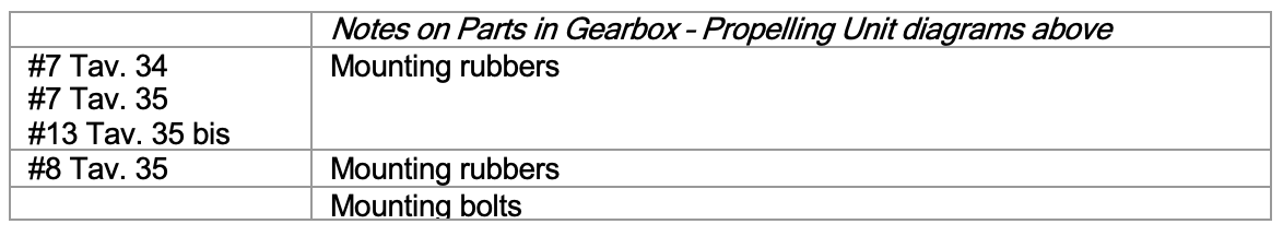
Nuts #8 torqued to 7.23 lb.ft. or 9.8 N.m. (Tool 8091139 – 10 mm)
Gearbox Selectors

Gearbox Oil Pump

The oil pump above was fitted to the second type of gearbox fitted to B20 & B24 5th& 6th Series cars
Overhaul Procedure continued
Check the lower shaft front-end spigot that enters the clutch centre support race. This shaft will wear away where it contacts the inner ring of the race & usually requires some chrome building up & regrinding to size. It is better to make this a firm tap fit into the bearing even though this makes re-assembly of the clutch a little more difficult.
The earlier model shafts were drilled right through, & a felt plug used in the front end to provide a little lubrication to the clutch spigot race. Do not remove this felt or disturb it in any way, as a clutch flooded with oil will result. Later shafts were not drilled beyond the sleeve supporting the 2nd speed gear synchromesh, & a little packing of grease was needed to keep the clutch spigot race lubricated.
Check the 2nd speed support sleeve bushes & the two drive faces that contact the 2nd synchromesh hub. These will be worn quite a lot after a big mileage. The bushes are not serviced as a spare part & if the need renewing, a complete part with the bushes already fitted will be needed; otherwise these bushes must be made & machined accurately to ensure quiet gear operation. The hub can be built up (with the Hitest rod) & hand fitted to refit.
Check & renew any worn or faulty oil seals, especially the one in the front casing, as the oil can find its way into the clutch if this one leaks.
Gearbox Pinions & Shafts
Tav. 32 below shows an identical layout to Tav. 31 for Series I cars but some parts differed in detail for different models.
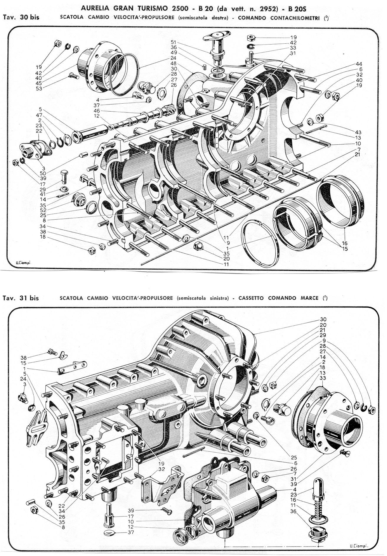
Tav. 32 bis - Gearbox internals as fitted to B20 & B24 5th& 6th Series cars
Crown Wheel & Pinion - Differential

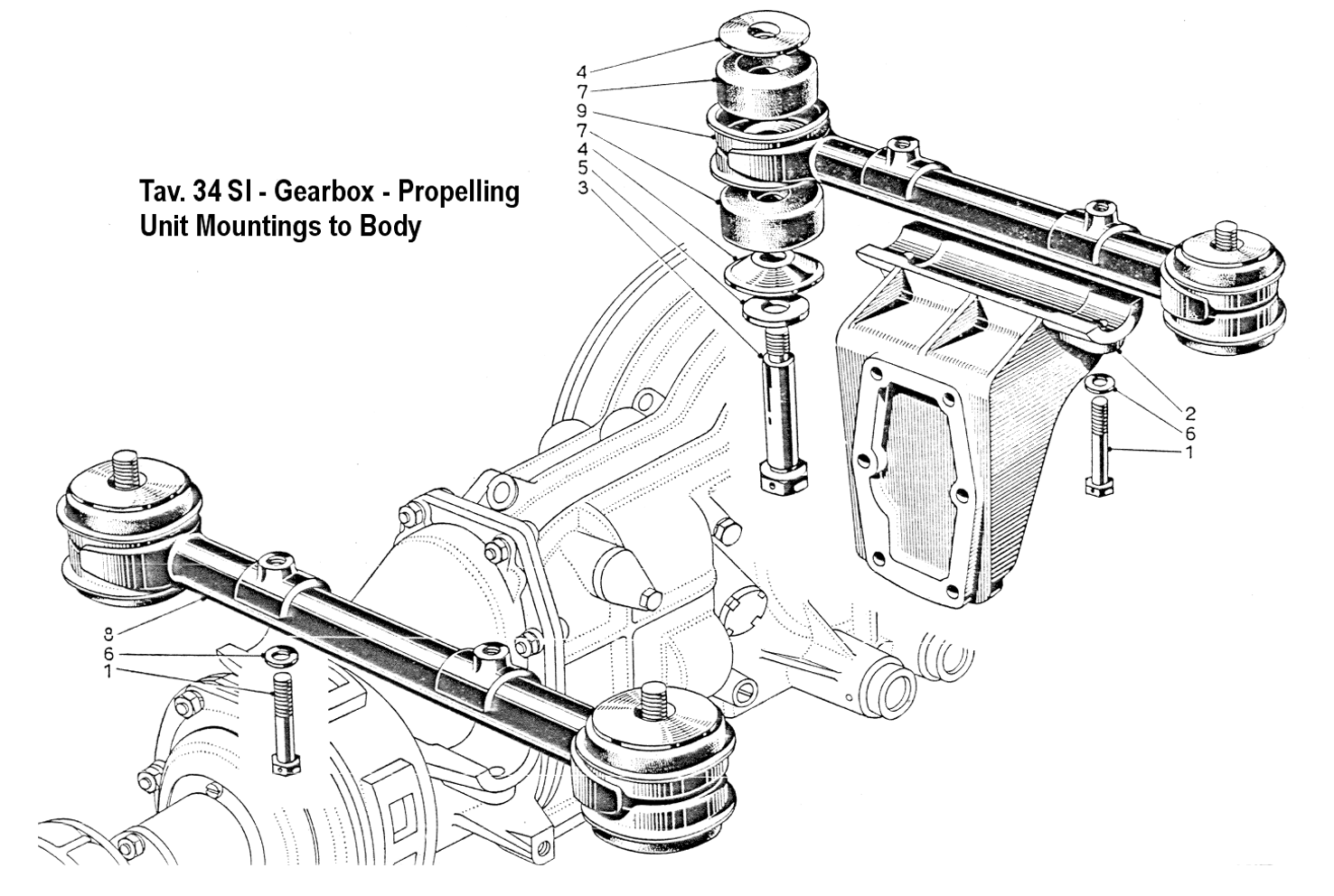
Tav. 34 for Series II cars above has the same layout as Tav. 33 for Series I cars with minor changes to certain parts

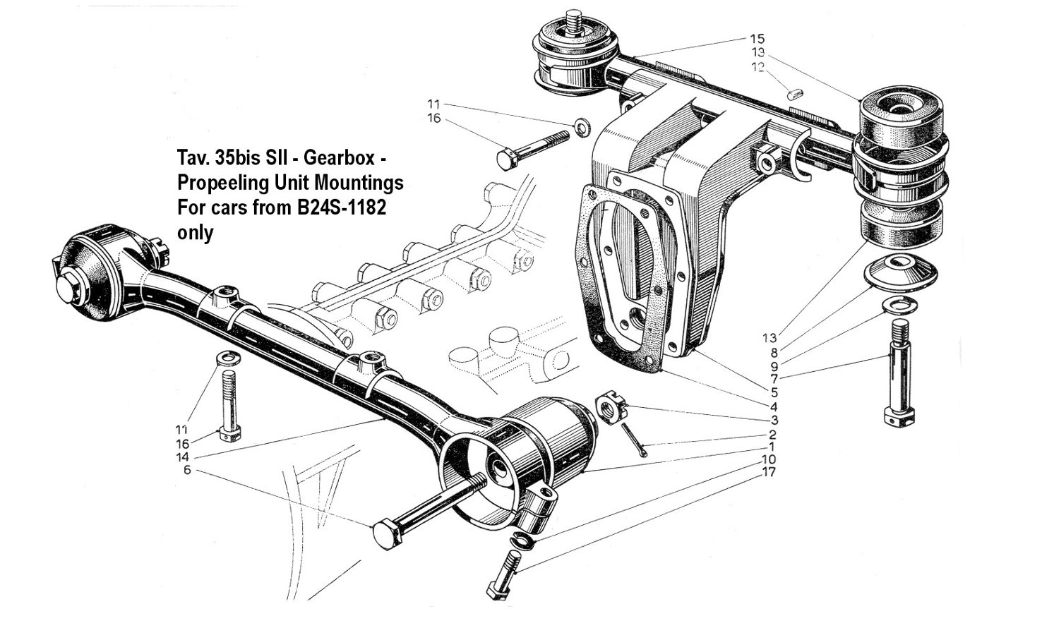
Tav. 34 bis above applies from B20 & B24 5th& 6th Series cars
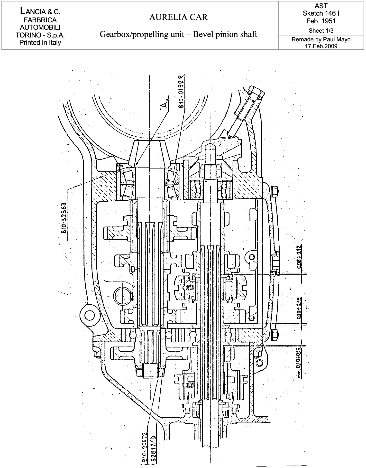
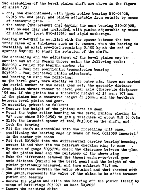
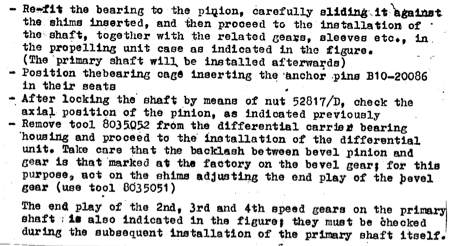
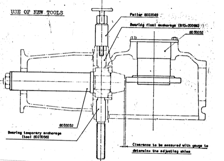
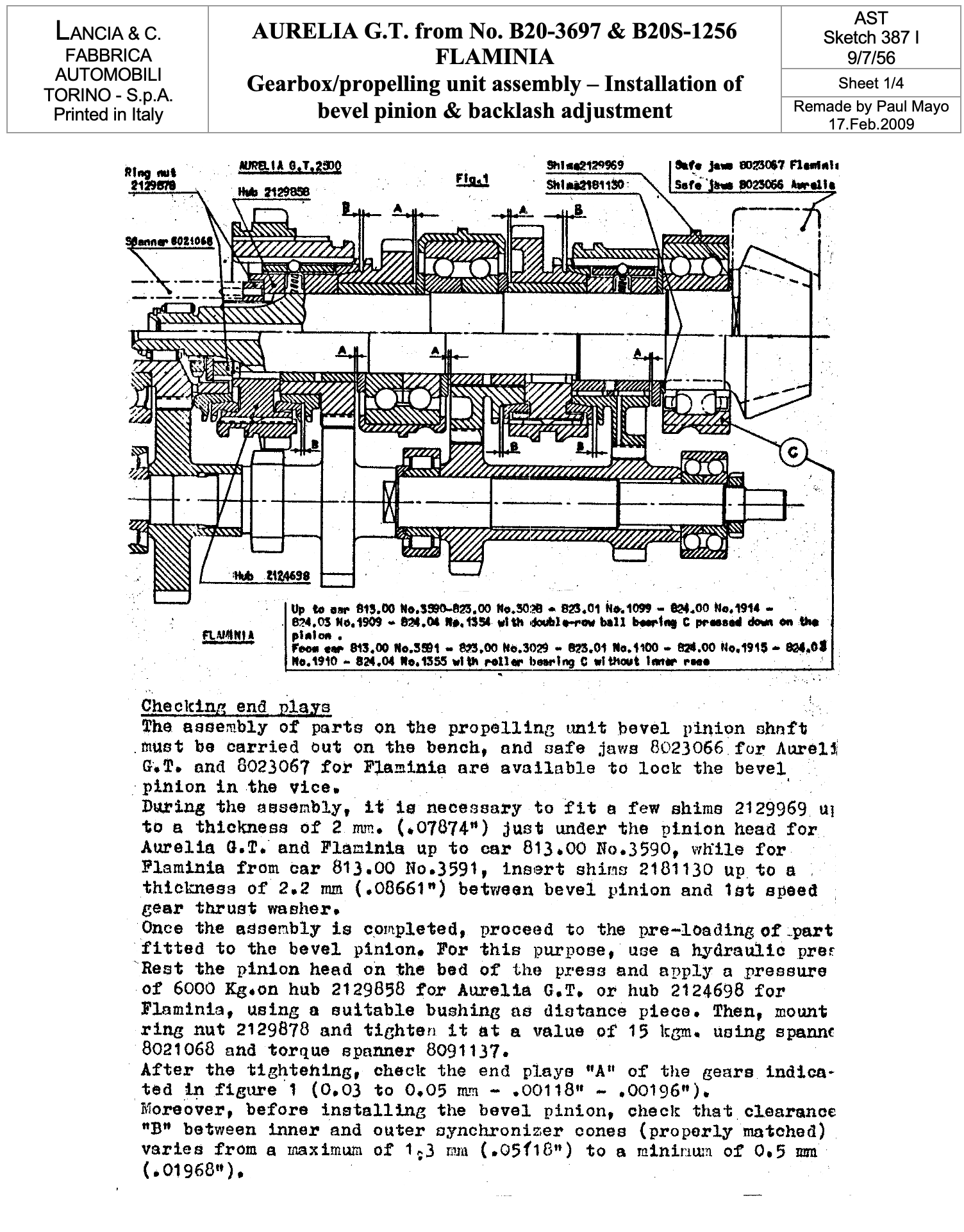
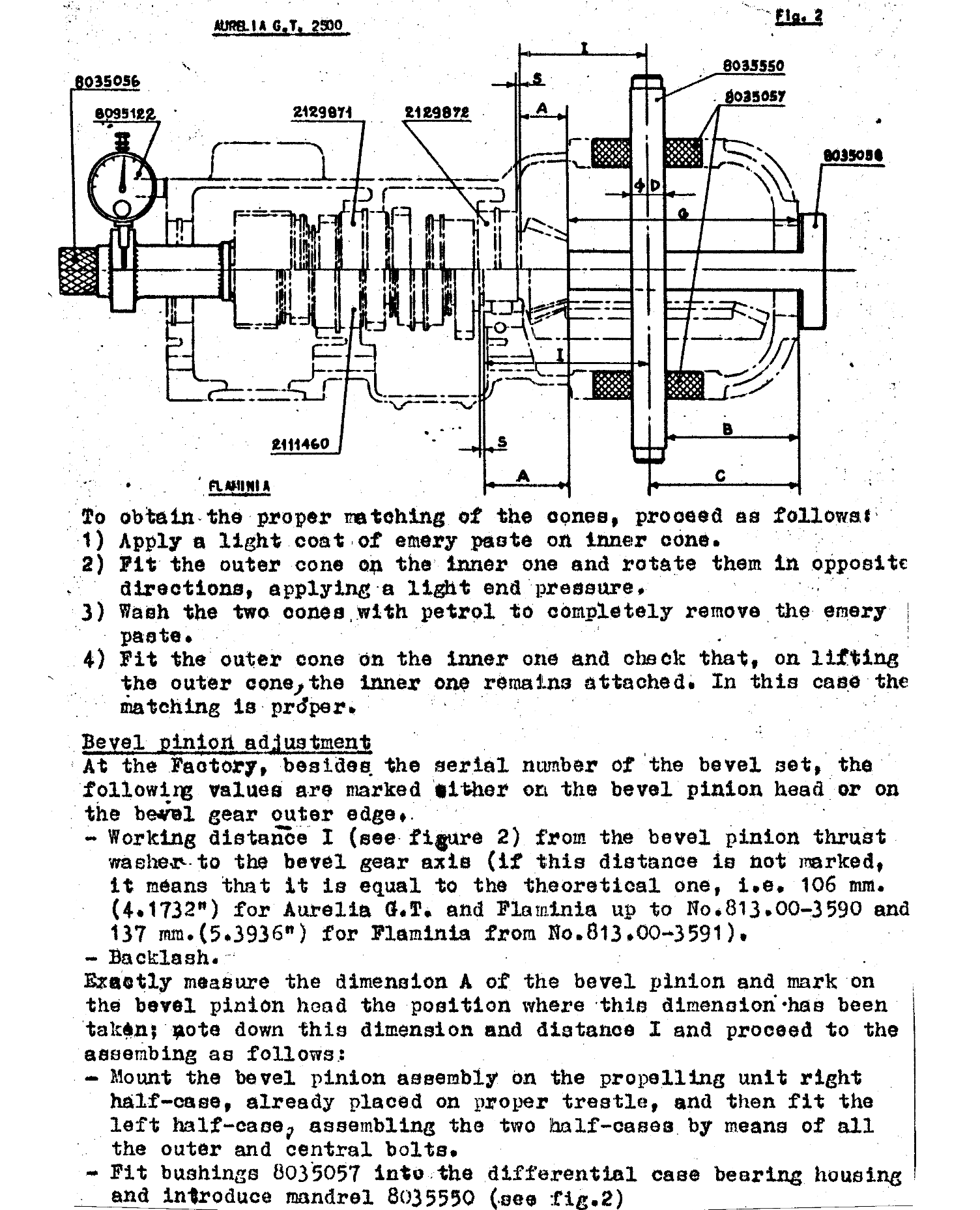
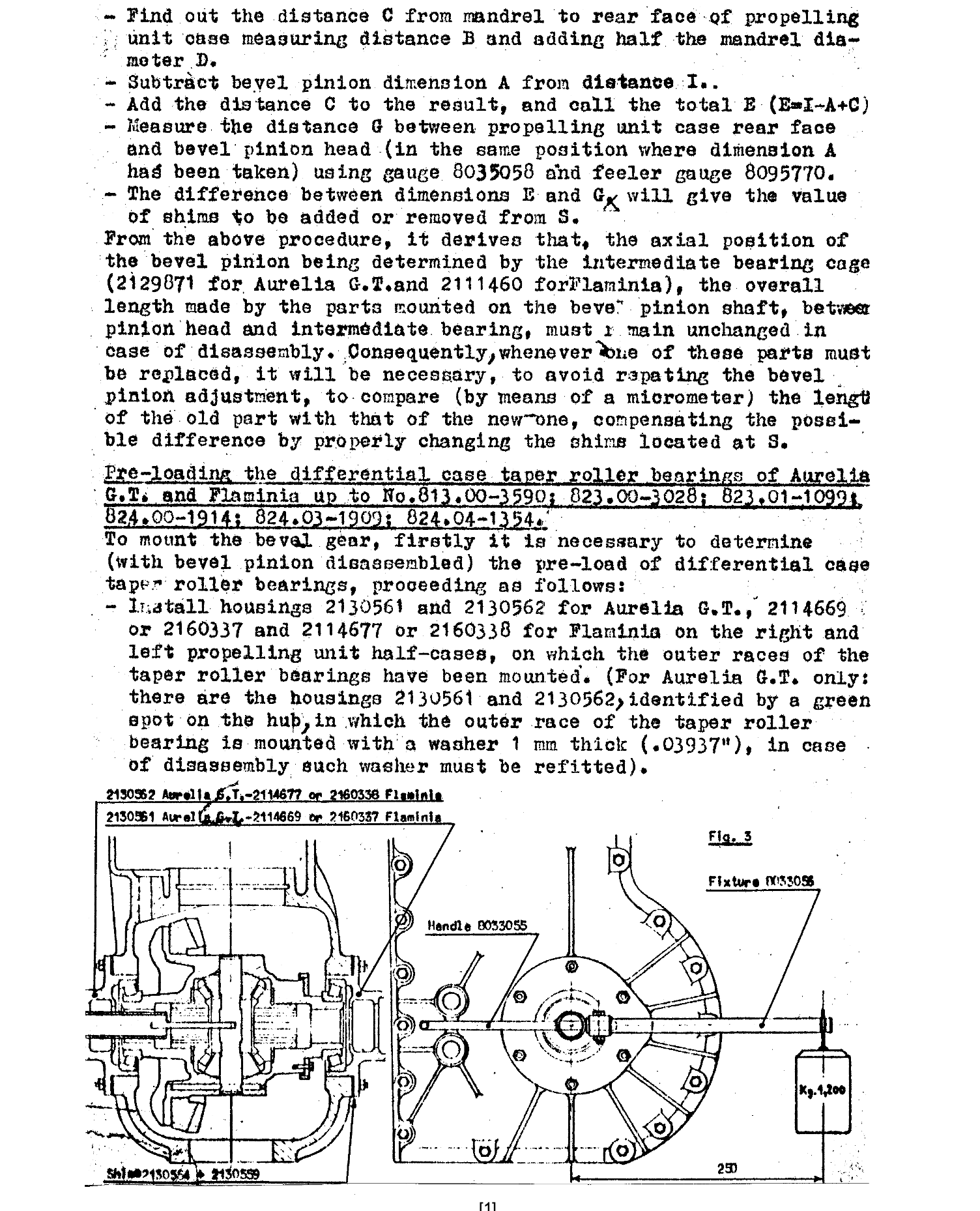
Gearbox/propelling unit – Bevel pinion shaft – Sketch 146 continued
Constant Velocity Joints & Drive Shafts

Aurelia SI Rear Drive Shaft (Tav. 51 SI Ref. 7)
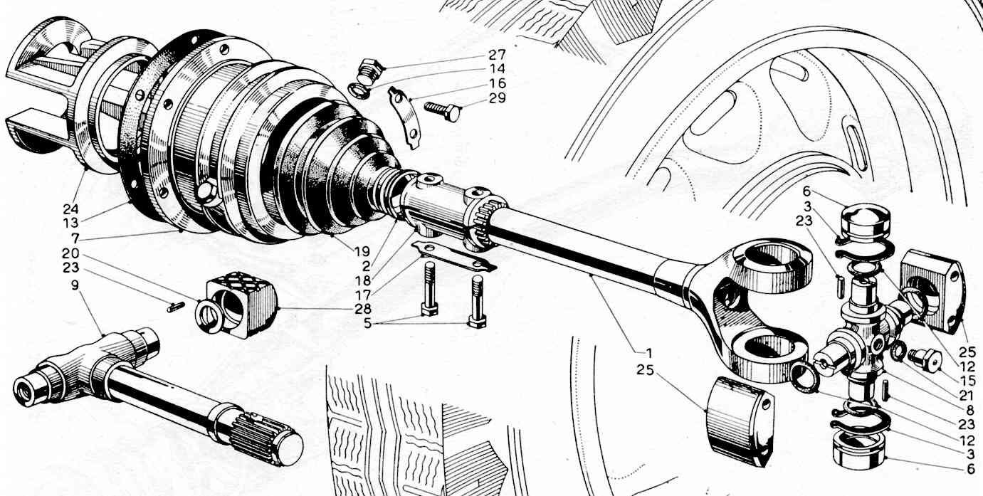
Aurelia SII Rear Drive Shaft (Tav. 52 SI Ref. 6)
Constant Velocity Joints
- The CVJ rubber gaiters are hard to obtain & were originally supplied by Pirelli. Flaminia rubbers fit 5th& 6th series cars. The gear shift gaiter from International Harvester truck part no. IH 301408CI requires modification to fit & is a temporary repair
- Parts 22126890 (Parts #12 in Tavs. above) are O-ring seals on outer CVJ & are same as Mercedes-Benz part 002 997 3645
- Joints should be checked for oil content & refilled every 3000 km with EP90 or equivalent. Never neglect & always ensure joints are firmly bolted to brake drums. After dismantling always renew gasket (#13) so that oil cannot get into the rear brakes.
- The needle bearings (#23) are RIV 9133302 (Lancia 2049415) & 280 are required for the 6 bearings. The needle dimensions are od = 3 mm, length = 11.8 mm
- Remember regular greasing of outer CVJ at greaser (#15)
- A Lancia improvement to the lubrication of the inner CVJ is described in Lancia & C. AST Sketch 531 I 6/8/1959. Six holes of 4 mm are to be drilled into housing 2116926 (Part #28 in Tavs. above). The following diagrams illustrate this:

Drive Shafts
- Rear brake judder at low speeds is not uncommon & is caused by play in the drive shaft splined joints (parts #1, #9 & #18). The splines must be a tight fit into the joint & the pinch bolts tightened to lbs. ft. Play in the rear wheel bearings may also have the same effect. Replacing these is difficult due to scarcity.
- Flaminia sleeve couplings also fit these shafts