Clutch
A single-plate Lancia-type clutch was fitted to all models up to and including the B20 4th series. B20/B24 5th & 6th series cars were fitted with a Fichtel & Sachs clutch with conventional clutch plate and release mechanism, which, for these cars, was hydraulically operated.
- The pedal mechanism remained the same throughout.
- The early clutch and housing varied between models and usually cannot be interchanged.
- Pedal rubber (7) – Volvo B18 is a good fit, but new replicas are available from Italy.
- Pedal shaft should be greased every 3000 km.
- Pedal free-play should be 15-20 mm for all models except B20 & B24, and 20-25 mm for B20 & B24 models.

- Clutch Pedal (Tav. 25 SI – Ref. 6, identical to Tav. 24 – Ref. 7 p121)
B10, B15 and B21 Clutch

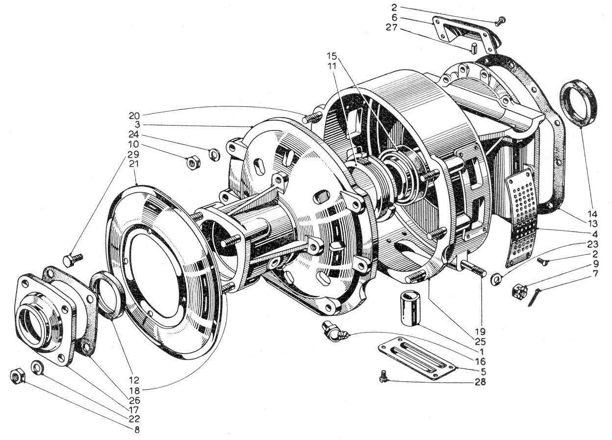
Tav. 25 Series I Clutch Housing
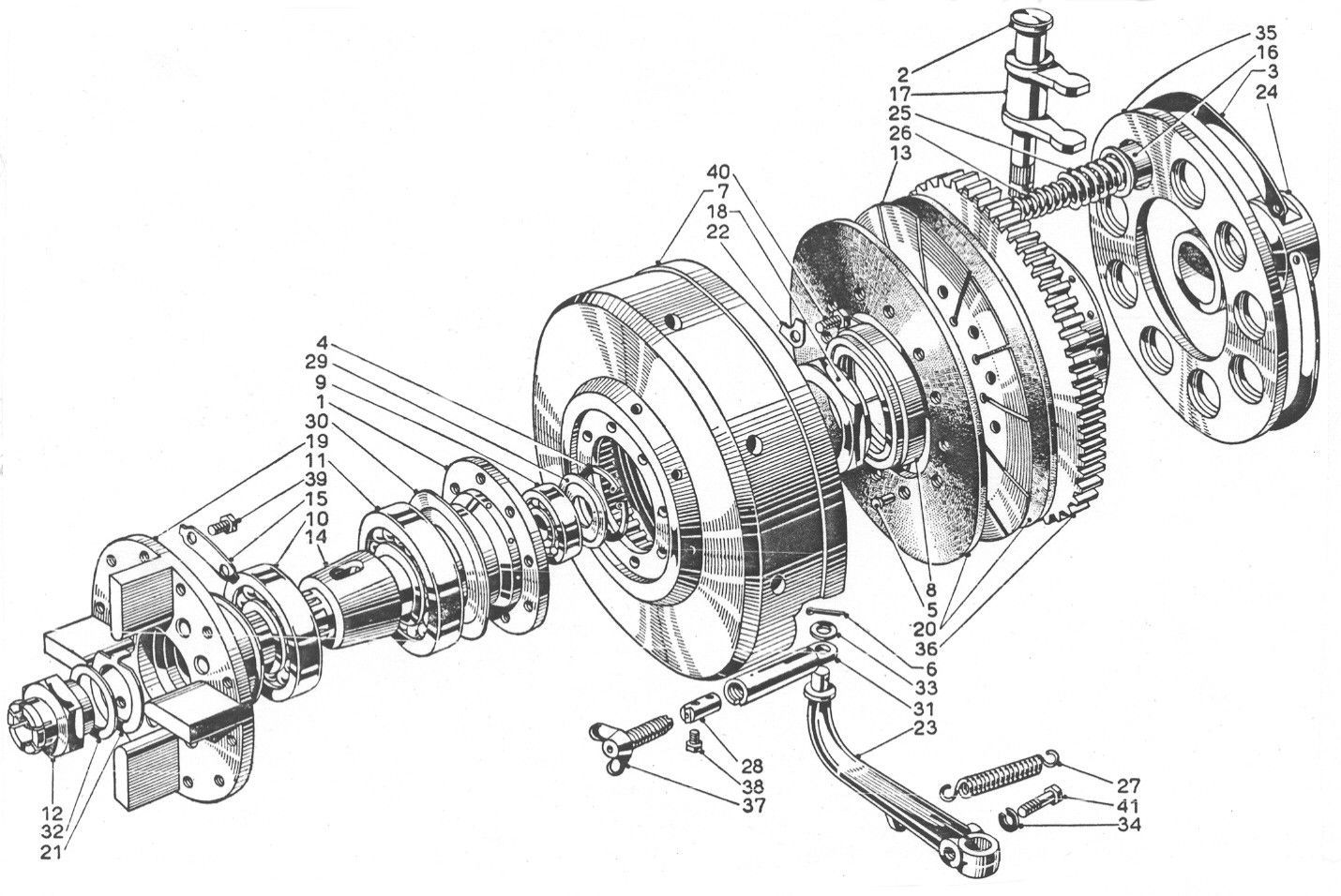
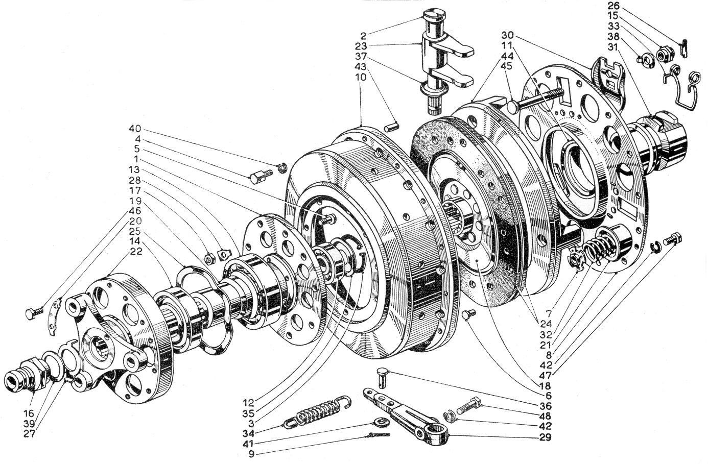
Tav. 26 Series I Clutch input and Clutch parts
Description - Notes in the table below refer to Tavs. 25 & 26 above
- Tav. 26 - The clutch is of Lancia design with body #7 containing friction discs #20 on support #13, & disengagement mechanism (#35, #36etc.). #36 is alloy with splines, which locate correspondingly in the body #7& is held in the body along with springs #25 & 26& allow cover plate #35 by a very large steel circlip #3.The B20 Series 3 clutch differed from Series 1 & 2 & B10 etc.& the whole unit is shorter than the B12/B20 Series 4 unit being 110 mm overall length. The greaser is also in a different location.
- Tav. 25 - 10 nuts secure clutch casing #26 to the final drive unit – 10 mm nuts across face are torqued to 7.23 lb.ft. or 9.8 N.m.
- Tav. 25 - 6 nuts secure the input shaft casing #3 to the clutch casing #26 – these are 10 mm torqued to 7.23 lb.ft. or 9.8 N.m.
- Tav. 26 - Input shaft #1 runs in 3 ball races:
Front race #10 – RIV 5B (Lancia 48051), 52 mm od, 20 mm id, 15 mm wide
Rear race #9 – RIV 03A (Lancia 48010), 32 mm od, 12 mm id, 10 mm wide
Centre race #11 – RIV 6B (Lancia 48044), 62 mm od, 25 mm id, 17 mm wide - Clutch springs #25 & #26 – There are 9 of each inner & outer. No data about the springs, as in Sketch 292 for later cars, has yet become available – PM September 2011
Tav. 26 in Series I Parts Book shows the following:
For B10, B50/51/52/53, B21, B15, B22 & B20 1st& 2nd Series
Outer clutch spring, #25 was part B10-18022
Inner clutch spring, #26 was part B10-18062 - Clutch friction plates –Parts #20 on 3rd& 4th series are 3.5 mm thick each side.
- Clutch input shaft greaser – refill every 6000 km
- Clutch thrust race #8 – is a ball race RIV 9671a (Lancia B10-0214AR), 72 mm od, 45 mm id, 16.5 mm wide.
The race is located in driven plate #36 by a very large nut #18 which is 50 mm size & screws into the withdrawal mechanism #24. This nut is torqued to 22.5 lb.ft. or 30.5 N.m. & can only be removed by a box or socket spanner as it lies in a recess. It can be made to last much longer by greasing with Bahdahl or similar chemical lubricant by lifting the side seal up a little. - Removal of Clutch Unit
Remove the rear section of the prop-shaft which can be detached by loosening securing bolts #6& shifting the rear prop-shaft section #2 on its splines along with the couplings #15, #16. Care must be taken with the spiders #12, which sometimes stick in their housings & can break if forced (see - Propeller Shaft & Mountings).
Tav. 25 – Remove nuts #8& pull complete unit #3 away which will expose the clutch cover#7 Tav. 26 containing the clutch. Compress the spring cover #35 Tav. 26 in a press or on a bench with cramps & remove circlip#3 Tav. 26. Carefully relieve the compression so that the springs do not fly all over the place. - Inspection & Overhaul
Examine the clutch & make replacements as necessary.
Check the pressure plate for flatness. If there are any scoring or burnt patches on the pressure plate & main housing they should be surface ground or replaced.
Check springs for pressure & replace any burnt or overheated springs.
A new lining will usually be all that is needed on the driven plate.
Check the spigot support race in the housing, & if it is rough or has been rotating on the clutch shaft on its inner diameter, then replace it as it will be worn, & can cause rough clutch operation.
Check the clutch release lever shaft in its housing bush & replace both if they are worn, as this will cause a shuddering clutch. The top bush for this shaft runs in the alloy casing & is not provided with any lubrication. Seizing of these parts will cause very heavy clutch operation & possible damage.
Inspect the thrust race #8 by removing nut #18 & drawing out the bearing. - Reassembly of Clutch
Reverse the removal procedure. Note that all rotating parts in the clutch were balanced & have marks, e.g. ‘o’ or paint marks (red) which should be lined up on reassembly. Grease all moving parts liable to seize.
Note that the proper location of the withdrawal forks #17 in #24 is vital, & is helped by watching the assembly of the entire units on its mounting studs #19 Tav. 25, through the inspection covers#4 or #5 Tav. 25, which may be removed. - Problems
Rusting of the friction plates to the cover on unused cars – just keep trying to break it – it can be done!The withdrawal mechanism can seize: forks #17 rust on to the pin #2, which will first require driving out of its splined location in the housing – a long job usually.
B12 & B20/B24 Series 4 Clutch
Description - Notes in the table below refer to Tavs. 26 & 27 below
- Although similar in design to the Series I unit, this clutch was modified to deal with the extra power from the new engines. The overall length between front& rear of outer case casting is 130 mm - longer & not exchangeable with a Series 3 unit.
- Instructions for disassembly, overhaul & reassembly – follow the instructions for Series I with the following notes in mind.
- Clutch Springs: This data is taken from AST Sketch 292 I (Various dates) plus research in the Spare Parts Catalogue. NB The B20/B24 5th& 6th series had a quite different clutch with 1 set of 9 springs.
Static Load
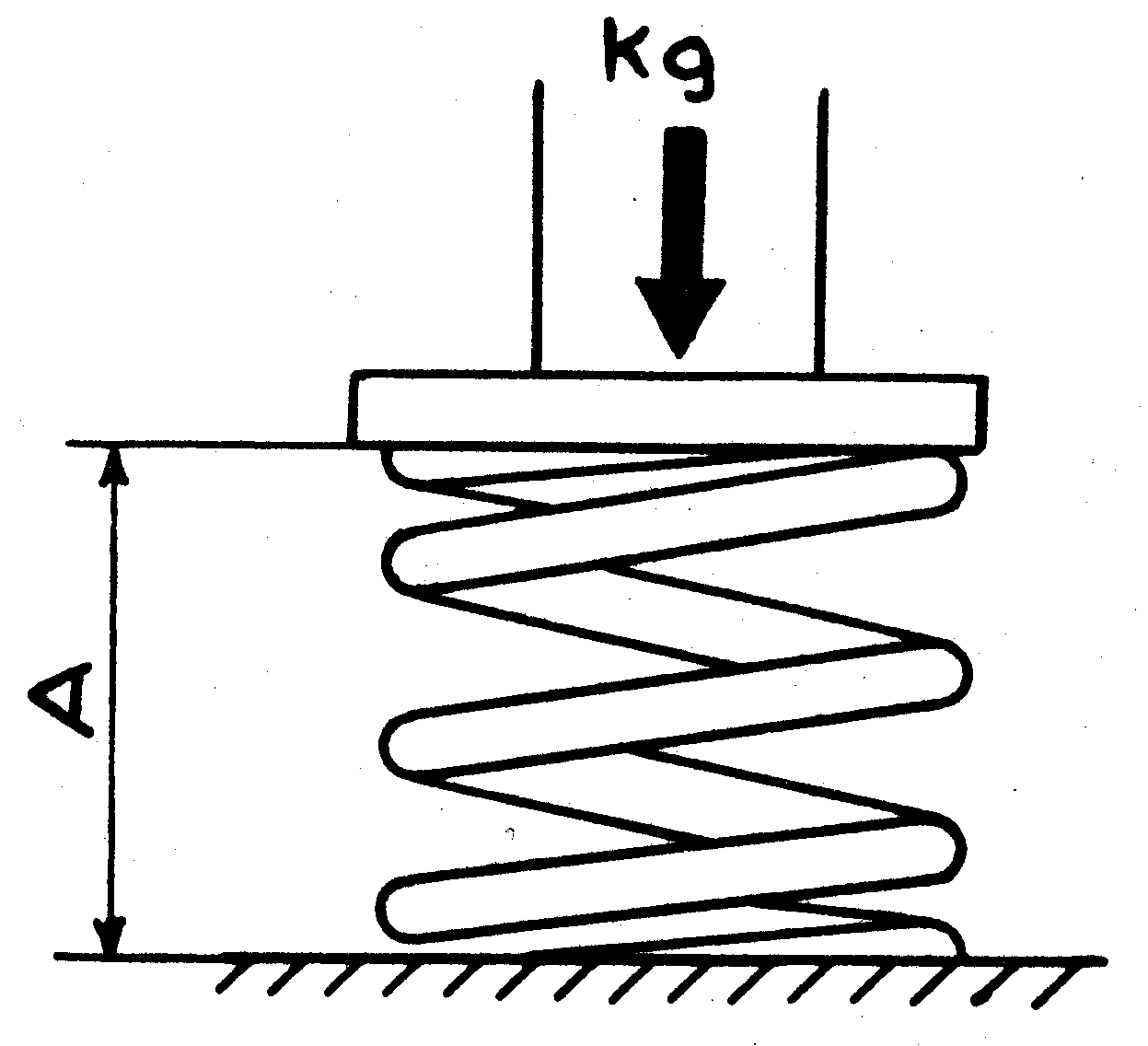
A = Spring Length, mm
From Sketch 292 I (28/3/59 mod.2 10/2/61)
| Spring Description | Tav. | Part no. old - new | Spring length A - under static load – mm | Static load – kg Normal, new | Static load – kg Min., old |
|---|---|---|---|---|---|
| B12 Outer spring | Tav.27#27 | B20-18022 - 82129727 | 38.5 | 31 - 32 | 30 |
| B12 Inner spring –earlier fitting | Tav.27#28 | B12-18062 - 82131648 | 38.5 | 11.4 – 12.6 | 11.4 |
| B12 Inner spring – later fitting | Tav.27#28 | B20-18062R - 82129758 | 38.5 | 19 - 21 | 19 |
| B20 3rd Series Outer spring | SI Tav.26#25 | B20-18022 - 82129727 | 38.5 | 31 - 32 | 31 |
| B20 3rd Series Inner spring | SI Tav.26#26 | B20-18062 -? | 38.5 | 15 – 16 | 15 |
| B20 4th Series, B24 & B24S 1001 to 1181 Outer spring | Tav.27#27 | B20-18022 - 82129727 | 38.5 | 31 - 32 | 30 |
| B20 4th Series, B24 & B24S 1001 to 1181 Inner spring | Tav.27#28 | B20-18062R - 82129758 | 38.5 | 19 – 21 | 19 |
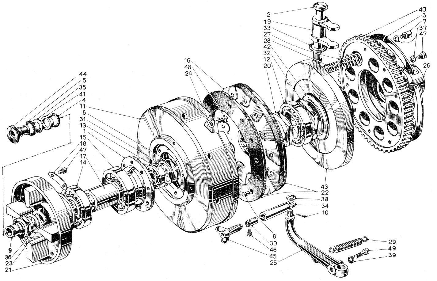
Description - Notes in the table below refer to Tavs. 26 & 27 below
- These clutches were often thought to be rather ‘soft’ by drivers & there was a habit of ‘beefing’ them up with 1/16” steel washers in the spring locations in the clutch cover #40 Tav. 27 below
- Thrust race - RIV 10103 (Lancia 48383) dimensions 72 mm od, 45 mm id, 19.5 mm wide
Probable equivalent is RIV 11162Car stopped at cars B20-3696, B20S-1255, B24-1059 & B24S-1181. - Clutch friction plates – They are 192 mm diameter Dated information on brands: Roulunds, Denmark No. 5-2084, quality Dantex.
Tav. 26 SII Clutch

Tav. 27 SII Clutch
B20/B24 Series 5 & 6 Clutch from cars B20-3697, B20S-1255 & B24S-1182
Major changes took place for these cars. A new Fichtel & Sachs modern style of clutch is used with hydraulic disengagement. The clutch pedal is now connected via the brake/clutch fluid reservoir to a clutch master & slave cylinder (see Tav. 27 ter below). The clutch mechanism is similar, if not identical to that used on the early Flaminia saloons types 813.00, 813.10-11. For pedal system see Tav. 25 above, page 02.5/01 except that part #21 now drives the piston of the hydraulic master cylinder (see below).
General Arrangement for Hydraulic Clutch System [Tav. 27 ter SII]

- Fluid reservoir for brake, clutch & front suspension – LH & RH versions
- Clutch slave cylinder
- Nut holding flexible hose to rigid pipe
- Flexible hose to slave cylinder
- Washer/seal between flexible hose & slave cylinder
- Bolt for union for reservoir pipe to master cylinder
- Clutch master cylinder
- Union for reservoir pipe to master cylinder
- Union for supply pipe from master cylinder to slave
- Washer/seal between rigid & flexible supply pipes to slave
- Bolt & washer fixing master cylinder to base
- Rigid from reservoir to master cylinder. This part changed from B20-3832 RH drive. All LH drive same part
- Rigid pipe from master cylinder to slave cylinder. This part changed from B20-3832 RH drive. Part changed from B20S-1500 (LHD)
- Bolt & washer fixing master cylinder to base
B20/B24 Series 5 & 6 Clutch from cars B20-3697, B20S-1255 & B24S-1182
Hydraulic Clutch Master & Slave Cylinders [Tav. 27 quarter SII]
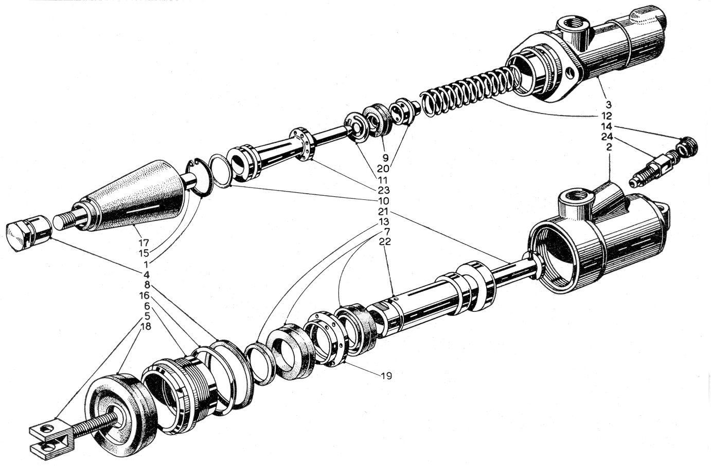
Description - Notes in the table below refer to Tav. 27 quarter above
- Part #3 is the master cylinder operated by the foot pedal. This part changed from cars B20-3832 & B20S-1500
- Part #2 is the clutch slave cylinder, mounted at the clutch housing.
- Parts #9, #10 are the master cylinder seals. #9 is the main seal of 35 mm od; #10 is an ‘O’ ring of 20 mm od.
- Parts #7 the identical slave cylinder seals. Replacements (Note from Australian Lancia Register Dec. 1989) – The size is 1.25” (32 mm? – see note 8 below) & part 003 997 5246 from a 1976 Mercedes Benz Model 14-18 commercial vehicle can be used.
- Part #12 is the master cylinder return spring. This part changed from cars B20-3832 & B20S-1500
- Retainer #20 & Piston #23 changed from cars B20-3832 & B20S-1500.
- #17 & #18 are the rubber boots/covers for the input ends of the cylinders
Repairing the Hydraulic Clutch Slave Cylinders
[by Les Rogacki, from the American Lancia Club, Lanciana Jan. 1973]
The aluminium corrodes to the degree that the pits cannot be honed out without going oversize. There are several approaches depending upon the condition of the bore. The original size of the bore is 35 mm or 1.3779”. First measure the bore internal diameter – if it does not exceed 1.384” a repair can be made using Method 1 below.
Method 1
Clean the bore thoroughly, say with a toothbrush & a solvent such as acetone or lacquer thinners. Clean the pitting very well. Dry.
Coat the bore with aluminium naval jelly for 20 minutes. Scrub pitting with toothbrush again ensuring jelly well worked in. After 5 minutes wash with hot water and dry completely. Avoid touching the poor with fingers
Mix about ½ teaspoon of metal filled epoxy resin. With a ¼” wide stick apply a thin coating of the epoxy to the entire bore, making sure the pitting is filled. Allow to cure until hard.
Place cylinder in a vice with the wide end titled up & filled with several teaspoons of water. Using a brake cylinder honing tool, hone the bore leaving traces of epoxy on the walls. Wash in warm water & remove all abrasives
Polish the brass piston. Clean all parts & holes & reassemble with new rubber cup seals. Apply a thin film of hydraulic oil to the moving parts before assembly.
Method 2
If the bore is very badly pitted or oversize, then it must be bored out & fitted with a steel sleeve. See the sketch below. The steel tube must first be processed & the outside diameter measured. The cylinder is then bored to a slip fit for the tube. A very small portion of the thread root may be machined when this is done. The machined cylinder should be cleaned with a solvent.
Cut the tube to the length shown. Coat with Loctite & insert into the cylinder. Be sure the sleeve is NOT pushed to the bottom. There should be some clearance as in the original cylinder. Allow the Loctite to harden. Permatex make a material similar to Loctite.
The hydraulic feeder hole should then be drilled through the steel sleeve. Match the existing small hole at the bottom of the hose connection.
The inside of the sleeve is now ready for honing to 1.376” plus 0.002 minus 0.000 diameter. The honing should be done with a common brake cylinder hone using light oil.
It is now necessary to remove the sharp edges from the hydraulic feeder hole. Use care not to scratch the bore. Clean & reassemble.
The reworked cylinder should be superior to the original & the Loctite will prevent galvanic corrosion.
I set a rather arbitrary maximum size of 1.384” & this may be too restrictive. The basic criteria are that the lips of the rubber cup seals should be in full 360º contact with the cylinder bore & that little pressure is required to move the piston in the cylinder. In operation the hydraulic fluid expands the cup under pressure to provide a good seal.
Before using epoxy I checked the resistance of epoxies to hydraulic fluids & this was confirmed in Machine Design mid-1972.
It may be possible to switch the existing rubber cups/seals as the rear cup gets little wear & maybe in good condition

Clutch Housing [Tav. 26 bis SII]
Clutch Internals [Tav. 27 bis SII]
Part no. old - new
Spring Description
Tav.
Part no. old - new
Spring length under static load – mm
Static load – kg, Normal, new
Static load – kg - Min., old
Part no. old - new
B20 5th Series car B20-3696 to 3816
B20S-1001 to 1256
B24S-1182 to 1332
Tav.27bis#32
B20-18022B - 82129729
37.8
57 – 63
53
Part no. old - new
B20 6th Series
B24S from 1333
There must have been a slight change in clutch parts for the 6th Series as the parts book seems to say that on ordering for the first time 9 of parts 81790880 (RH Drive) or 81790881 (LH Drive) should also be ordered.


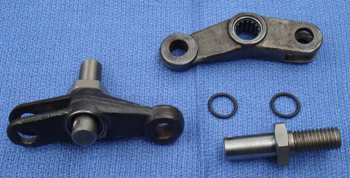
Aurelia Clutch Lever
All Aurelias except the 5th and 6th Series B20s have a mechanical clutch operating mechanism. There is a small toggle lever mounted on the pedal box (No1 in table 24 in the First series Parts Book) which changes the ‘push’ of the clutch pedal to ‘pull’ so the action can be transmitted to the clutch throw-out lever by a stout wire, similar to No. 8 fencing wire. This toggle is heavily loaded and runs on a 12mm pin with no lubrication. The result is excessive wear in both Chris Long’s B20 and Bill Renou’s B10 (I haven’t looked at my B10 yet). This is in contra-distinction to the clutch and brake pedals which have large, bronze bushed and well lubricated bearings.
I considered bushing the toggle with bronze and making a new pin but lubrication would still be a problem. I found a drawn cup needle roller bearing measuring 12mm wide x 14mm OD x 10mm bore which fills the bill nicely. Chris Long’s toggle was so worn it wouldn’t clean up at 14mm so I filled the worn side with nickel bronze before boring it. Because of the irregular shape of the toggle I made a jig so the toggle could be mounted in the lathe, centred and squared. It was straightforward to bore it to 14mm. I made new pins from mild steel and had the working surface case hardened. The toggle is 14mm wide so there is room on either side of the roller bearing for a 1.5mm O-ring to retain the grease and seal out dirt.
I expect no further trouble.
Peter Renou
(Added to Workshop Manual online 17-September-2025)
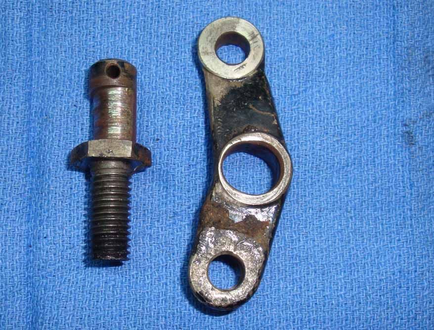
Badly worn clutch lever and pin

Repaired lever with needle roller bearing inserted