Lighting System
| Headlamps & Fog lamps |
|---|
| Front lights & Flashing Indicators |
| Rear Lights & Reversing Light |
| Interior Lights |
Headlamps – Controls
B20 Coupe headlamps are controlled by the lever on the steering wheel (the same lever as for the indicators). When pulled backwards, the lever returns with flashing light; when set forward, the lever is kept in position providing anti-dazzle lighting.

Switch control of dipping lights & indicators: Right-hand Drive
A = Anti-dazzle light
L = Anti-dazzle flashing light
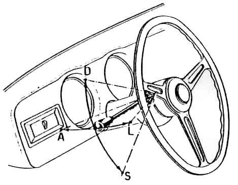
Switch control of dipping lights & indicators: Left-hand Drive
D = Control for right indicator
S = Control for left indicator
B24 Convertible headlamps are controlled by lever on the instrument panel. When pushed downward, the lever returns to the original position with flashing light; when moved upward, the lever is kept in position giving anti-dazzle lights
Relay for Headlamps
Carello Headlamps 170 mm diameter Tipo 00.591.000
Used on various Appia models & Aurelia GT 2500

Also see note below. These lights completely dismantle to a separate glass lens & plated reflector. A difficulty in re-using these lights is the obsolete type of headlamp bulb fitted to the reflector. The hole will not take an H4 type of bulb without modification. An appropriate H4 reflector fitting can be removed from a donor reflector/sealed beam unit & soldered to B20 reflector #8 without removing the existing bulb fitting. The mounting bowl #16 has only one hole for the headlamp wiring only.
Carello headlamp glass lenses seem to be dated February 1953 for 3rd& 4th series, & April 1955 for 5th& 6th series
See page Electrics 08.8/07 for details of the weather seal between #2 or #3 above & the front wing.
Carello Headlamps 170 mm diameter Tipo 07.591.000 & 08.591.00
Special application used on various Appia models & Aurelia GT 2500 instead of Tipo 00.591.000

This later type was fitted to later 4th Series B20 etc. #3 in diagram above is a sealed beam unit & can still be obtained new (2012). #8, the headlamp bowl, mounted onto the wing differs from the earlier type above in having a projection at the rear which has 3 holes, one 20 mm & two 17 mm in diameter. Special rubber grommets were fitted originally, which held L-shaped brass tubes, through which the wiring passes. With this bowl all the wires to the headlamp, front side/indicator lights & fog light pass through the top, larger hole & tube & are then re-directed from the bowl to the relevant lights through each of the smaller holes & tubes. The larger tube is 13 mm OD & the smaller tubes 11 mm OD

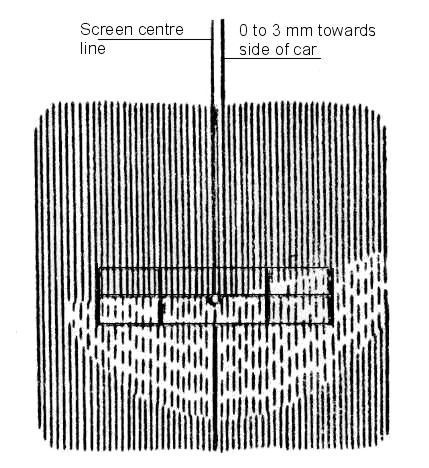
Headlamp aiming continued
For high beam adjust laterally so that the vertical axis of the beam is on the centre line or slightly displace towards the side of the car to a maximum of 3mm – see Figure 3.
Having taken care not to alter the vertical aim, check the dipped beam again. Then adjust the other headlight.
If the seating of the headlamp or the headlamp itself is defective it will be impossible to set-up accurate aim of the beam.
Headlamps with asymmetric dipped beams: Follow above procedure and ensure that the horizontal part of the beam is on the centre line & that the change of angle occurs at the vertical centre line or up to 3mm towards the side of the car. For cars in countries with left-hand drive roads the inclined section of the beam should be on the left instead of the right. See Figure 4.
See below for adjusting Fog-lights
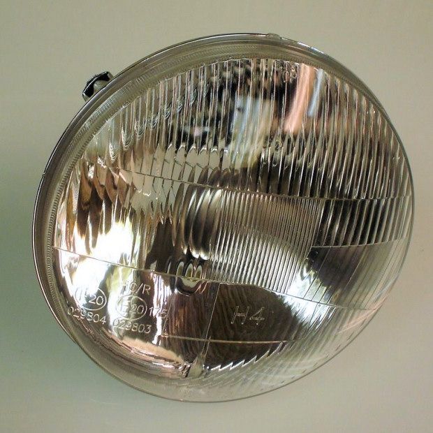

A modern (2012) replacement headlamp for a B20, available with, or without a parking light & to fit H4 bulbs – see www.classiclancia.com & elsewhere
Carello Sidelights from B20-2401 & B20 GT2500
Side-lights (parking lamp plus indicator) applied to Aurelias were as follows:

Fog-Lights - (Proiettore fendinebbia)
The B10, B15, B21, B22 & B24 variants did not have separate fog-lights. The B12 had a unique fog-light. The B20 models all had fog-lights fitted, but there were two types specified in the Spare Parts books as follows. From B20-3352 & B20S-1101 the wiring arrangements to fog-lights changed requiring more parts.

Adjusting Fog-lights
To adjust the aim of the fog-lights the required inclination is given by the ratio between the distance in mm of the lamp centre from the floor divided by 200 – e.g. the Aurelia GT 2500 lamp centre is 605 mm from floor, inclination is 605/200 = 3.025%.
Adjust the aiming device close to the relevant inclination referring to the following table. Aurelia GT 2500 is 3.025% = 2º = 42 inches/100 feet

Switch on the fog-lights & adjust their vertical aim until the geometric horizontal axis of the beam is on the horizontal centre line of the aiming device. To adjust the fog-lamp aim, loosen the fog-lamp mounting bolt inside the front wheel arch. Unless lubricated these bolts will rust & seize-up. Originally there is a stud fixed to the back of the lamp bowl with a nut & washers.
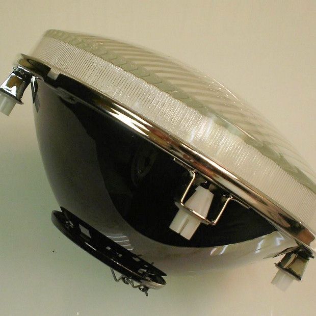
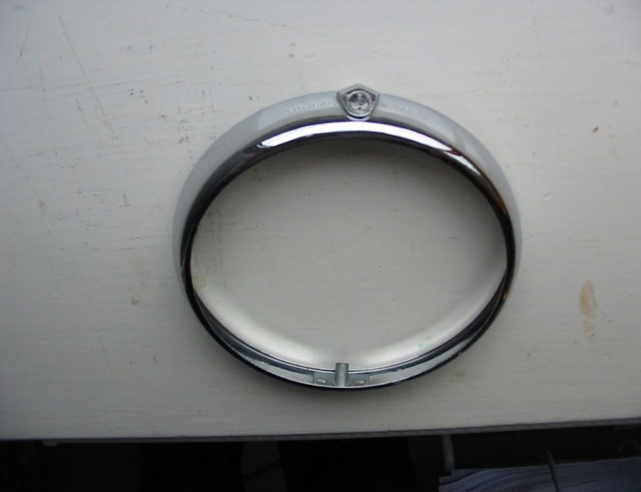
The following shows the later B20 type of Fog-light Carello 02.071.000
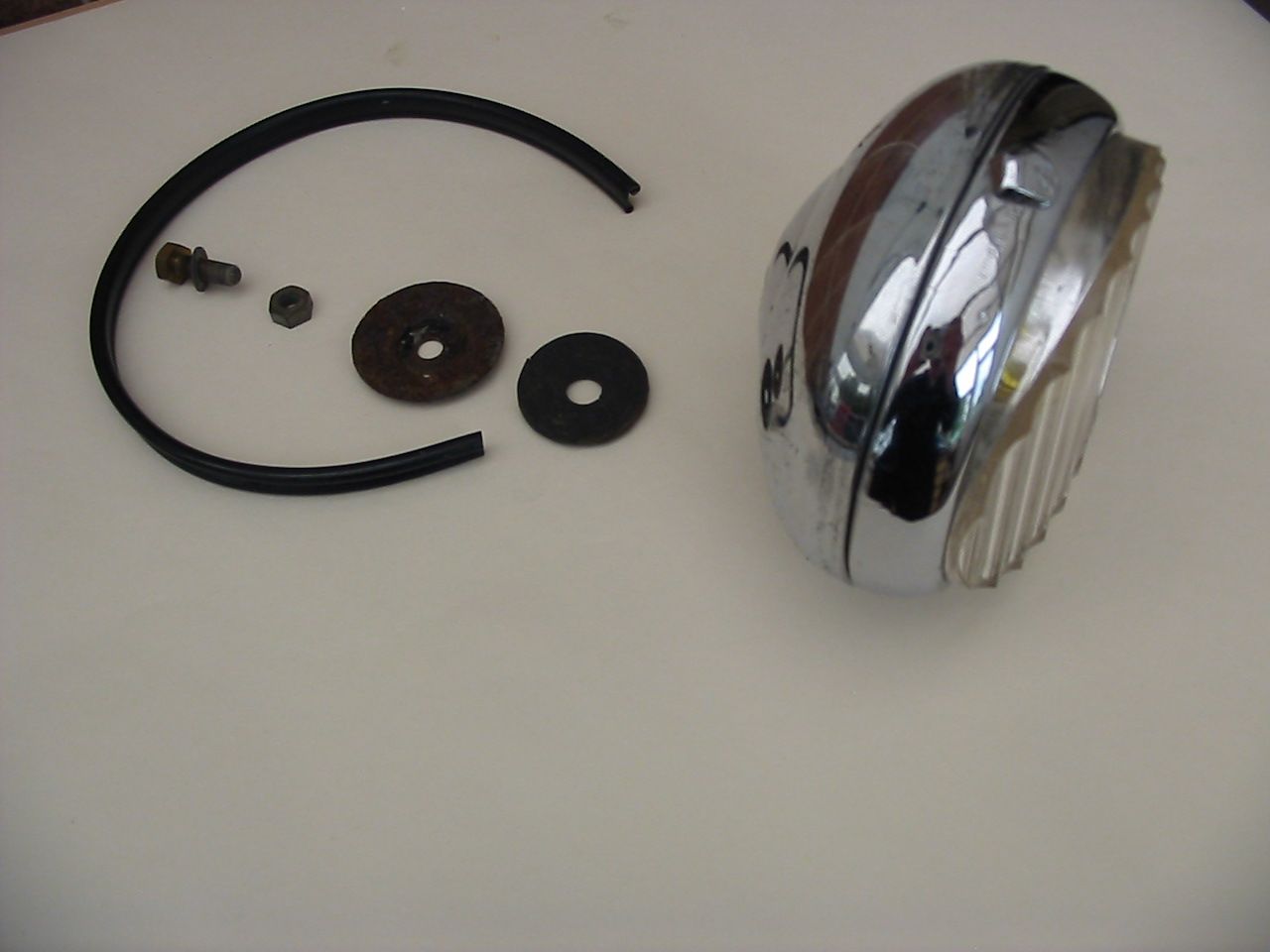
Fog-light assembled, with seal, mounting bolt & nut, rubber & metal washers.
In this case the original fixed mounting stud has been replaced by a bolt & nut.

Front view of fog-light
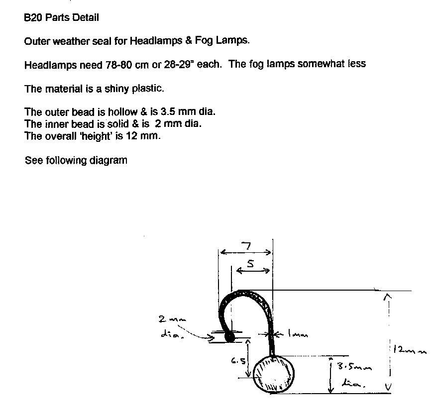
B20 parts details:
- Outer weather seal for Headlamps & Fog Lamps.
- Headlamps need 78-80 cm or 28-29 inches each.
- The material is a shiny plastic.
- The outer bead is hollow & 3.5 mm dia.
- The inner bead is solid & is 2 mm dia.
- The overall "height" is 12 mm

Inside Fog-light body showing Earth terminal to bulb on left & wiring connector 31 on right. In centre is supply terminal to the bulb marked 56a.
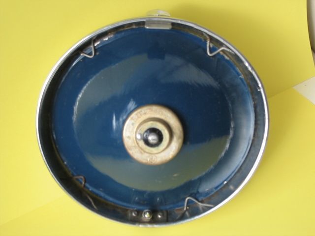
Reassembled reflector (painted blue – not original) with bulb & clips to hold into chrome bezel.
The screw which mounts the bezel on to the body is special.
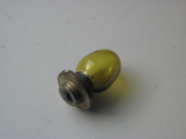
Fog-light bulb – A 12 Volt 50 Watt bulb
Part 5611110 white
Part 2176067 – Yellow coloured on Series II cars.
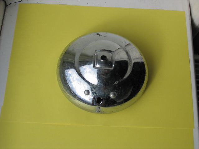
Rear of fog-light body with fixed stud mounting missing.
Hole at bottom is for electrical supply to lamp & there should be a rubber grommet through which the wire(s) run.
A = Head of screw = Slotted 6 mm diameter
B = Shoulder of screw = 7 mm long, 2.5 mm diameter
C = Thread of screw = 7 mm long
D = Point of screw = 2 mm long

This is Fog-light chrome bezel – external & internal views text.
Rear Lights & Reversing Lamp
Rear Lights


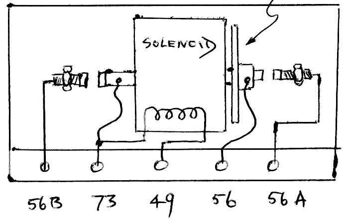
TESTING FLASHER RELAY BOX - Notes contributed by John Savage
Tools & equipment required
- 12 volt battery
- 2 off 21 watt 12 volt flasher bulbs
- 1 off 5 watt or 21 watt bulb to check brake stop-light operation
- Connecting wire with 5 mm plug ends to connect above items to box
Setting Up
Flashers:
- Connect lead from 31 to Battery negative terminal
- Connect a lamp to Pin 4 & earth
- Connect a lamp to Pin 5 & earth
- Connect Pin 2 to Battery positive terminal – nothing should happen
- Connect another lead from Battery positive terminal to 54S – the two lamps should now flash
Now -
Connect the two lamps to Pins 6 & 7 & move the Battery positive lead from 54S to 54D – the two lamps should flash again.
This completes checking right & left flasher operation
The flasher pilot light in the instrument panel is connected to Pin 3 but is only used in early models. Late Series 4, and 5 & 6 have two lights (for left & right) connected with the front (not rear) indicator lights – see wiring diagrams. New, replacement flasher boxes with 2-pin flasher units will have two diodes connected to Pin 3 & going to Pins 4 & 7 respectively as there are no modern 3-pin flasher units small enough to fit in the original box.
Brake Light Circuit
Connect a positive supply to Pin 1, connect lamps to Pins 5 & 6, earthing the lamps – the lamps should light continuously. When the positive lead is connected to either 54S or 54D as in the previous test the relevant light should go off. It will not flash, as the flasher is not energised in this test.

Many other rear light units were fitted as contemporary or later substitutes such as the Alfa Romeo items detailed below. Volvo B18 (Part no. 276528) could be used but is rather too big. It has a 3-part lens, max. width of bezel 100 mm, max. length 205 mm.
The following show three non-original fittings to B20 1st& 2nd Series:
Altissimo Tipo 279.01.00 also about 6 inches long but more oval in shape in plan view & slightly curving in section was also used. This model had a clear lens for a reversing light so that three bulbs were used in total. This type was also used on the Alfa Romeo Guilietta

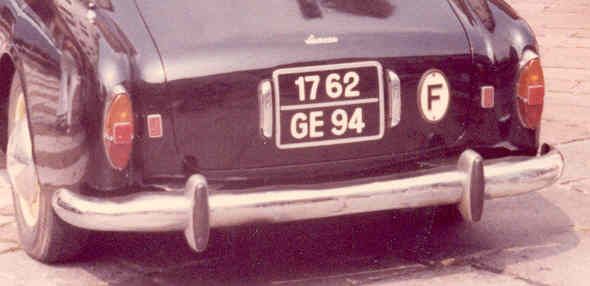
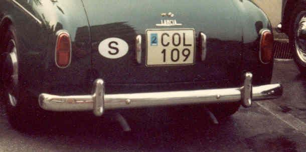
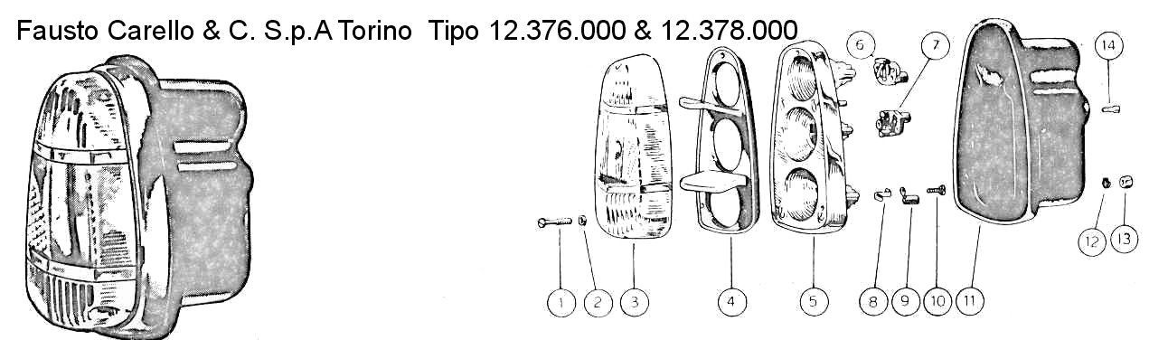
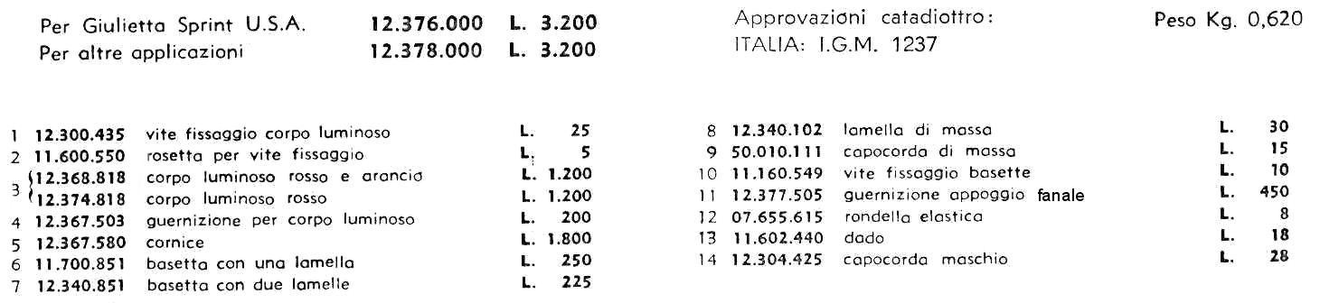
Carello type 12.400.717 (red) & 718 (amber) were used on many earlier cars & was larger in all dimensions being about 6 inches long with a flat surface & thick plastic lenses with reflector & separate flasher bulbs. Carello unit Tipo 12.378.000 shown below is similar but was an application for Alfa Romeos. The Carello catalogue is dated November 1959:
Reversing Light
A reversing light was fitted only to the B12 & 4th Series B20/B20S. It is a Carello part (18.701.000, Lancia part no. B12-90082, later 82133491 – see Tav.58 #19).
It is located in the centre of the rear valance below the rear bumper on a circular, vertical, flat base pressed in to this panel.
A minor modification was suggested by John Tillotson (Australia) to increase the amount of light when reversing the car. If you have fitted a replacement flasher unit, but retained the original Carello flasher control box, take the wire from the reverse switch to the original reversing light where it passes through the flasher box area. Cut the wire & introduce a connector to which another wire is attached the other end of which is taken to Terminal 1 on the Carello unit.
This change will turn on both flasher indicator lights when the reversing switch is on.

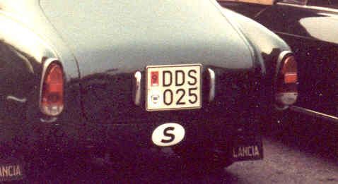
Rear of B20-3255 in 1977 in poor condition showing mounting holes
for rear lights, reversing lamp & boot lid handles
Interior Lights & Switches
All saloon Aurelias have interior lamps mounted in roof side panels. These are unbranded items.
The 4-door saloons (B10, B21 & B12 series) have both door-switch & dashboard switch controls
The 2-door coupes have only a dashboard switch control& the open cars also have internal lights operated from the dashboard.
See the wiring diagrams page to see the location of these items on the cars.
For all saloons & coupes the complete interior light unit is the same item, part no. B10-90030/1 (old) / 82128569 (new). See Tav. 58 for Series I& Tav. 68 for Series II models.
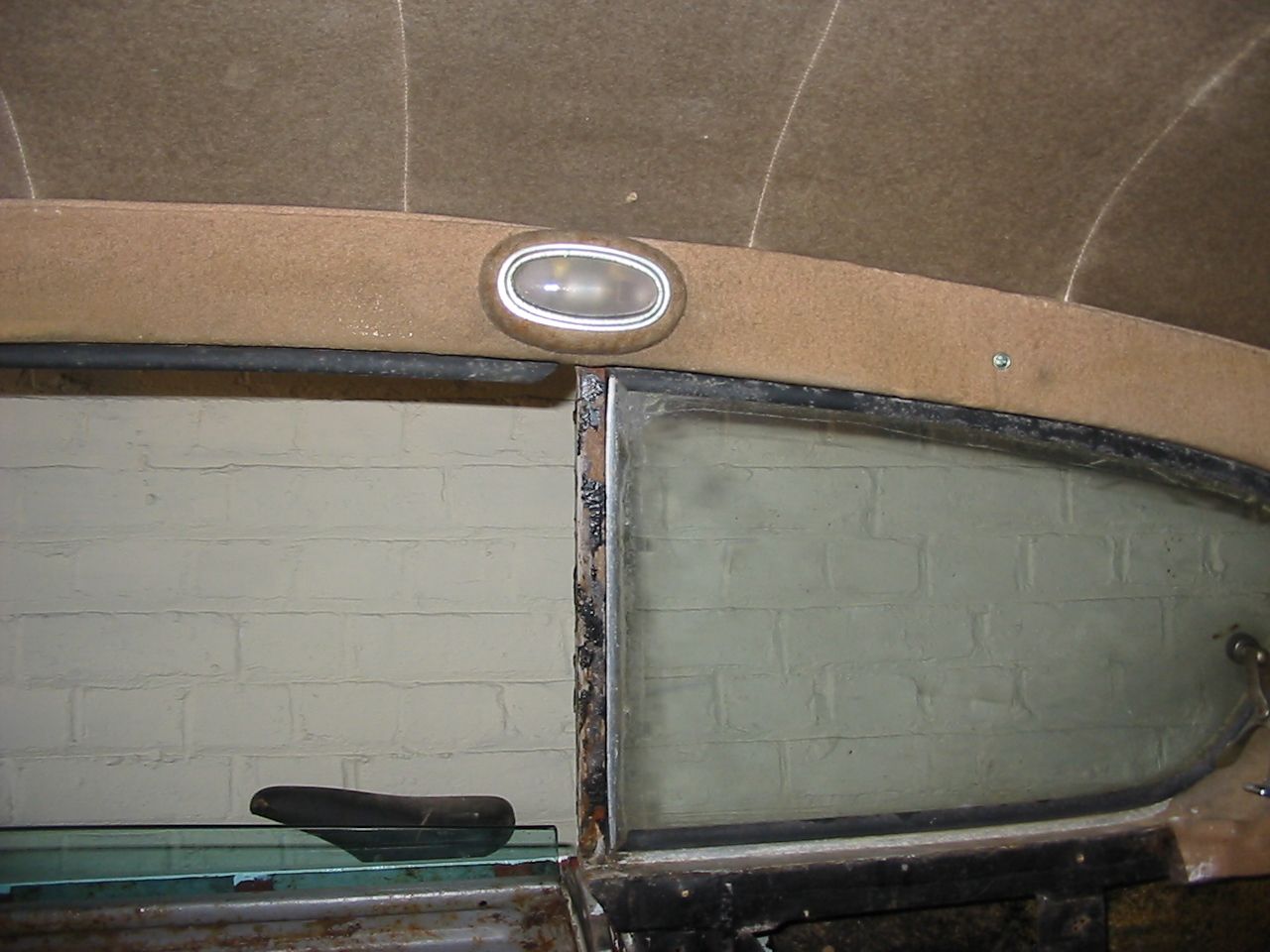
From Right Side of an Unrestored B20 4th Series
From Right Side of an Unrestored B20 4th Series
Outside view of unrestored example showing chromed bezel & frosted glass lens. This item is a push fit into its base.
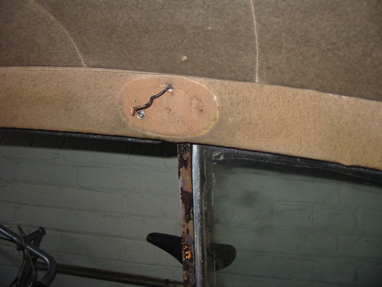
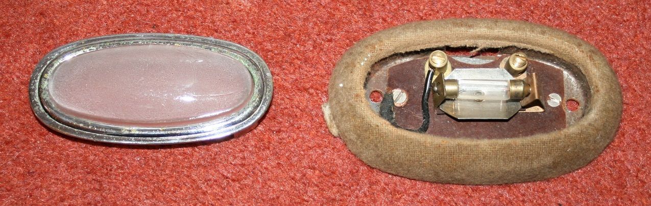
Outside view of unrestored example showing lamp base covered in original "Panno Nocciola" (beige cloth) with light bulb & electrical fittings mounted on a Bakelite base, which screws on to the metal base. The black wire takes the circuit to earth into the metal base & thus through its mounting screws to the car body.
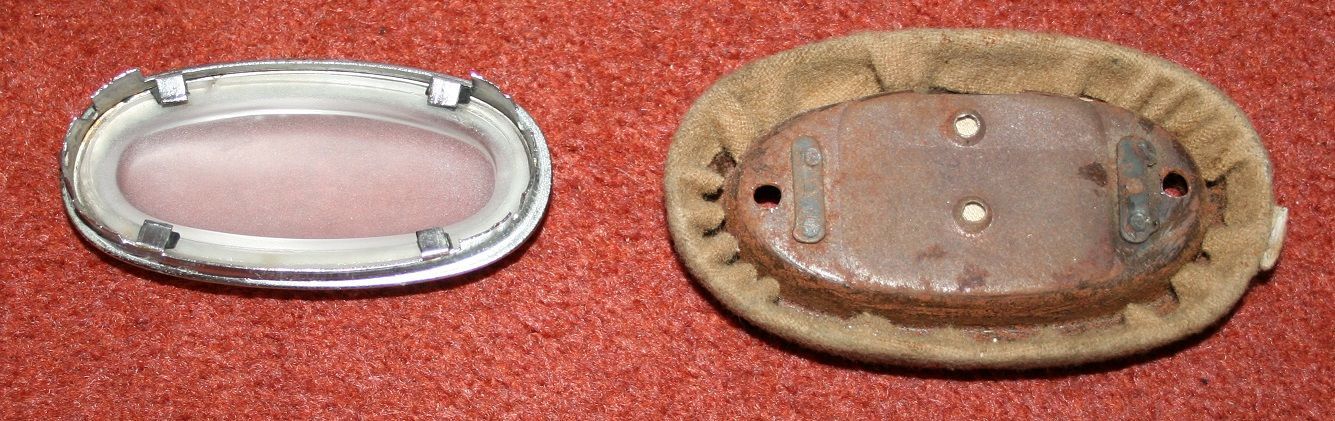
Inside view showing the tabs retaining the glass lens. Note the 4 small rubber protectors under the metal tabs. These are made from 3mm black rubber rod section. Total parts = 6
Inside view of lamp base. Total parts = metal base, cloth covering, 2 mounting screws, Bakelite electrical base & fittings including 2 brass screws for wires, 2 wires & the 3 Watt bayonet light bulb = 10
On restoration or electrical overhaul a choice is to install an earth return wire to the battery. The supply wire comes through the slot in the centre of the top of the base.