Cylinder Heads & Rocker Covers
The overall design of the Aurelia cylinder heads was similar but differed in each type. One large physical change on the 2.5 litres B20 engines from the 3rd series on was that the rocker units are mounted diagonally rather than longitudinally as on the earlier, smaller capacity engines.
Tav. 1 – Engine – Cylinder Head & Rocker Cover – B12

Parts Review
| Tav.1 - Part No. | Description | Comment |
|---|---|---|
| #02 B10-1110 - B10, B50-series, B21, B20-1st Series 2125824 - B12 2129478 or B20-1110 - B20 2nd to 6th Series& B24 | Rocker covers | |
| #03, #14, #18 | Exhaust manifold fixings | See 'Exhaust System' |
| #05 & #17 3414142 – B12 3414302 – B20 4th on 3414301 – B24 | Domed closed nuts for rocker cover | B20 – these are plated, possibly nickel plated on B12 & chrome plated on later B20 engines. Washers #17 are also plated, 2 mm thick 15.7 mm od & 8.25 id. |
| #07 2131617 – B12 2129544 – B20 & B24 | Cylinder head gasket. Originals are copper-asbestos & mm thick. | Modern replacement copper-asbestos gaskets can be thinner, & experience shows less reliable. Solid laser-cut copper gaskets are also a possibility. |
| #11 | Lock-plate | may be replaced by the curved part no. 82116068 used on the Fulvia gearbox output shaft bearing retainers |
| #15 - 3151201 | Inlet manifold studs in head – shorter 6 x 1.25 mm metric in head, 6 x 1.0 mm above head, length above head = 15 mm, depth in head = | B12 – x8 each side B20 – x6 each side |
| #16 - 3151211 | Inlet manifold studs in head – longer 6 x 1.25 mm metric in head, 6 x 1.0 mm above head, length above head = 17 mm | B12 – x4 each side B20 – x4 each side. On 2 engines observed these are fitted on the upper side except the middle stud which is short. |
| #24 | Cylinder head fixing plain nuts | These are 8 mm thick with 14 mm hex flats. |
Removal & Reassembly of Cylinder Heads
The following notes are based on experience with 4th, 5th & 6th series Aurelia B20s, and apply to engines installed in right-hand-drive cars. Some notes on left-hand drive cars are included.
Removal of Left-hand Cylinder Head
- Drain water from the cooling system. Disconnect heater hose from the tap and remove windscreen washer reservoir (x2 10 mm bolts and spring washers: one below regulator, the other approached from below after removing the radiator grille). Remove spark plug lead conduit tube, with leads (x2 10 mm bolts and washers)
- Remove x4 14 mm nuts and washers holding the inlet heating manifold to the inlet manifold. Disconnect petrol drain at block.
- Loosen top hose clips. Disconnect 7 mm nuts and bolts holding the hand-choke linkage. Disconnect throttle linkage. If non-flexible, disconnect the fuel line at the carburettor (17 mm brass union with fibre washers on each side). Remove air cleaner, carburettor with heating manifold, or if fuel line flexible, swing the assembly to the right side.
- Remove x4 14 mm brass nuts and steel bolts and washers holding the exhaust manifold flange to the front exhaust down-pipe. This is best done from below after jacking up the car and thoroughly soaking the bolts and nuts with penetrating oil. Two spanners are required, as the bolts will spin. One spanner should be short, open and narrow. The front two bolts are head down and the rear to head up. Remove and inspect rectangular copper-asbestos gasket.
- On left-hand drive cars it should not be necessary to take the exhaust manifolds off the cylinder heads. Removal of the heads can be done by undoing the head nuts from the head in the order shown below.
- Remove x3 14 mm domed nuts, and washers holding rocker cover down, and lift off with its reinforced rubber gasket. Inspect the gasket.
- Taking each rocker unit in turn with its pair of push-rods, loosen and remove x2 14 mm nuts and double, tabbed locking plate which hold the rocker unit to the cylinder head. Keep these parts in order that they may be exactly replaced after careful inspection for play and rotating surfaces.
- Loosen and remove the x16 14 mm nuts and flat washers from the head studs and keep in correct order by placing in a box or using adhesive tape.
- Gently pull up the cylinder head squarely on its studs, avoiding spillage of oil. (See separate notes below on removal of stuck cylinder heads and worn studs.
- Carefully free off the cylinder head gasket (which may be copper, but is usually copper-asbestos) all round the edge and gently lift up avoiding distortion. Inspect carefully for damage and blow-by between cylinders and waterways.
Removal of Right-hand Cylinder Head
- Drain water from the cooling system. Remove spark-plug lead conduit (x2 10 mm bolts and washer) with leads.
- As for left hand side
- As for left hand side but carburettor must be completely removed.
- As for left hand side but in addition, loosen and remove the x6 14 mm brass nuts and steel washers holding the exhaust manifold to the cylinder head. Penetrating oil should be used on all these studs and the lowers ones are best approached from below using a short spanner. The upper left-hand stud must also be removed otherwise the manifold fouls the steering column during removal.
- As for LHS
- As for LHS
- As for LHS
- As for LHS except that raising head must be done in such a way that the exhaust manifold falls free during the lifting of the head. Remember to retrieve the 3 copper-asbestos manifold-to-head gaskets.
- As for LHS and sections 10 and 11
- Check that the cylinder head face is absolutely flat using an engineer’s flat plate. If it is not flat it must be surface ground, followed by lapping it against a surface already known to be flat – another good cylinder head is a possibility.
- The circumferential groove about 3 mm from the edge of the combustion chamber in the head surface, and in the block should be cleaned. It is there to help ‘nip’ the original copper-asbestos head gaskets and promote a gas- and watertight seal. Check also the 2 holes in the heads for the locating dowels in the block on each side.
- Look for silting up in the coolant spaces, and for cracks and leaks around the exhaust ports. Whilst able to inspect inside the block check for corrosion of the liners, presence of oil & in particular if the tapered steel coolant distribution tubes on each side are intact. On some engines these may have entirely disappeared. New ones are to be inserted from the front after removal of the large core plugs either side of the timing chest cover.
- Reassemble the exhaust manifolds to the heads in all cases except the RH head on RH drive cars. The gasket fitting between cylinder head and manifold is very close to the similar item on Flavias.
If both heads are to be removed, combine the sets of instructions.
For the LH head
- Using gasket cement, coat the gasket around each bore, the top of each liner on the block and the combustion chamber on the head.
- Slip the gasket down the studs, making sure it fits evenly. Check that the locating dowels are pushed through the holes in the gasket and that they locate into the head fully when it is pushed down the studs.
- Reconnect the petrol drain underneath the inlet manifold. Then fit the washers and head nuts to 20.25 ft.lbs. or 27.5 N.m as in the data below.
- Valve assembly: (see
Valve Gear for more details) - It may of course have been necessary to check/overhaul the valve & rocker gear. Refit the pushrods, check that the valve caps are on the inlet valves, and refit the rockers in their blocks, the tab washers and the nuts, tightening these also to 20.25 ft.lbs. or 27.5 N.m
For the RH head
- The general procedure is the same as above but it is vital to fit the petrol drain after you have started to slide the head down the studs, but before it is more than about a quarter of the way home. This is because it is impossible to get one’s hand into the ‘V’ of the engine to fit the drain after the second head has been fitted.
- Fit the petrol pipe to the fuel pump.
- On RH drive cars fit the exhaust manifold.
Final Assembly
- To avoid air leaks in the manifolds, check by using a straight edge that the two inlet manifolds present a level face to single manifold you have left attached to the carburettor. Using gasket cement, attach the inlet manifold complete with the carburettor.
- Refit the HT leads and conduits, water hoses, choke and accelerator linkages, petrol pipe to carburettor union.
- Check that the valve tappet clearances are correct and that the spark plugs are clean and properly gapped.
- Refit the air cleaner, refill with coolant, and check the oil and all connections, before starting engine.
- Subsequently the head nuts will have to be re-torqued at least once, the first time after a brief running of the engine. Settling of the head gaskets and possibly of the head studs can reduce the torque considerably, which will result in leaks of oil/water if not attended to.
Cylinder Head Data
Nuts
1. Nuts are all 14 mm hexagonal plated steel originally.
2. Nuts at positions 8 10 and 16 are flat nuts. See Tav.2 #20 Part no. 3411101. 6 required with 6 plain washers Part no. 2057184
3. Nuts at positions 1 2 3 4 5 6 7 9 11 12 13 14 15 are domed nuts. See Tav.2 #12 Part no. 2052842. 26 required with 26 plain washers Part no. 2057184
4. The modern standard is to use 13 mm nuts on 8 mm studs but for the sake of originality it is best to keep things as they were, if at all possible.
Studs
1. Upper thread size is 8 mm by 1.0 fine metric
2. Lower thread size in block is 8 mm by 1.25 metric. Drill size is 6.2 mm or 1/4 inch.
3. The stud lengths vary:
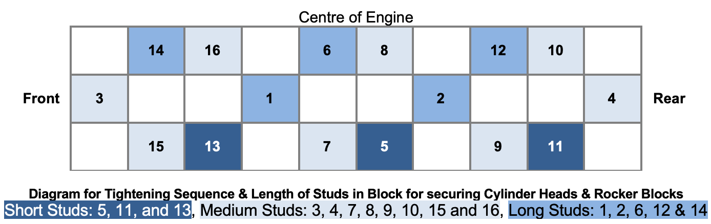
4. Short Studs: 5, 11, and 13 are 90 mm/3.5” with 65 mm/2.5” above the block surface
5. Medium Studs: 3, 4, 7, 8, 9, 10, 15 and 16 are 115 mm/4.5 inches with 85 mm/3.375” above block surface
6. Long Studs: 1, 2, 6, 12 & 14 are 120 mm/4.75 inches with 95 mm/3.75” above block surface
7. The studs are slightly tapered at the lower end of the shank. This is a vulnerable point subject to corrosion. Inspect carefully once head is removed. Stud threads were rolled, not cut. It is important to use rolled threads at upper end of studs (i.e. as on all new bolts).
8. The tops of the original studs have an un-threaded nose, which helps to guide the head on to, & protect, the stud threads. In using re-manufactured studs, it is essential that the lower section is not over-cut. Otherwise the stud will not screw down to its shoulder if the hole is not deep enough, leaving threads proud of the block surface, or if the hole is deeper than the threaded part it will screw down too far, leaving too little stud above the surface.
9. The holes in the block for the studs are approximately 35 mm deep for 25-26 mm of stud consisting of about 17-18 mm from the nose to the end of the threads plus the reduced section above.
10. Various stud oversizes were available originally (see Tav. 2 in spare parts catalogue).
11. For the B12 engine there were 3 extra sizes for studs #19 & #20: 10 x 1.5 M root (the section in the block), 8 x 1.25 M, 0.2 mm oversize & 8 x 1.25 M, 0.4 mm oversize
12. For the B20 engine (from car B20-2952) there was one extra size for studs #19 & #20 listed being the same as the B12 part 8 x 1.25 M, 0.2 mm oversize.