Propeller Shaft & Mountings
Arrangement for B10, B15, B21, B20 Series 1, 2& 3 [Tav. 35 SI]
- The prop-shaft is in two parts (1) and (2)
- Ball race (9) is RIV 5 BB: 20 mm id, 52 mm od and 21 mm wide
- Nut (10) is 30 mm & should be torqued to 86.8 lb.ft. or 117.7 N.m.
- Nut & bolt (6, 11) holding couplings on to splined shaft ends should be torqued to 29 lb.ft. or 39.3 N.m.
- Couplings & spiders (12, 15, 16) on assembly should be hand-pressed together before tightening nuts & bolts (6, 11). To prevent squeaks and to help assembly the spiders may be coated in talc. This will also help with disassembly
- The two couplings (15, 16) must be parallel to one another: the gap should be equal at top & bottom. If this is not so, then the prop-shaft will not be in true alignment with the engine or propelling unit and may be evidence of crash damage. Collisions at the front of the car or even engine seizure can result in altering the engine mounting supports. True alignment is essential for smooth running of the prop-shaft, otherwise dreadful vibrations will occur.
- The couplings are anti-vibrators for this engine-speed prop-shaft & not universal joints.
- Wear in the bronze bushes (4) will also cause vibration.
- Lubrication is through greaser (19) and its cover (8) is easily lost if not well secured with a washer. Multi-purpose grease should be used every 6000 miles.
- The centre mounting (3) is located to the floor by bolts (5) holding cover plate (29). Spacers (13) are essential and lie between the cover plate and the floor of the car. This allows the centre mounting to ‘float’ with ‘play’ of 3 to 5 mm. This is essential to the smooth running of the prop-shat and it is not correct to tighten the centre bearing right up to the floor.
Balancing
The entire propelling unit including the engine, flywheel, prop-shaft components & couplings, clutch input shaft & clutch housing are balance during manufacture & assembly. Balance marks are seen variously stamped on the faces of metal components as ‘0’, ‘1’, ‘2’ etc. or as painted lines usually in red.
It is thus vital on disassembly to assure yourself of the presence of these marks or to introduce new marks so that reassembly may be correct. Changes in the weight of or introduction of new components will usually lead to rebalancing.
Rebalancing may be done by trial & error but is better done by a specialist using electronically assisted dynamic balancing equipment. In the past the availability of appropriate jigs has been a problem but recent experience in the UK it that there are enough well-equipped specialists able to carry out this work.
Weights should be added or removed from the couplings (#15 & #16) as were the factory counter weights (#14). Threaded holes are provided for this in the couplings.
Wear & Overhaul
Wear is either due to irregular greasing of the centre bearing, continued use with an un-balanced prop-shaft, hard, long & competition use & of course very high mileages. The following may need attention:
Rubber spiders (#12) – these can crack & disintegrate at the centre & introduce play into the coupling. Three spiders are used on all early cars, some models had more.
Centre bearing (#9) – this may wear normally as any ball bearing race. On reassembly ensure that the greaser is cleaned & refilled. The bronze bushes (#4) are also important items to wear & may well require replacement.
Rubber seals (#18) – these may prevent the proper retention of grease if worn or missing, or may allow the entry of dirt.
In very bad cases of misuse, the splines & coupling bolts may have worn & become damaged
Propelling Shaft for Aurelia Saloons B12 & B22
These models have a prop-shaft similar to the B10 except that the shaft (#1) is one piece with two floor mountings each with a greasing point & only two rubber spiders are used at each end.

B12 & B22 Propeller Shaft (Tav. 36 SII – Ref. 6)
B20, B20S, B24 & B24S 4th Series
The following diagrams and notes apply to chassis B20-2952 to 3696, B20S 1001 to 1255, B24-1001 to 1059 and B24S-1001 to 1181.

Fig. 27 from Ref. 8 p54
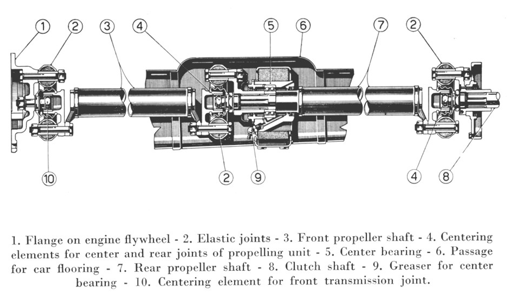
- Flange on engine flywheel
- Front rubber spider
- Front propeller shaft
- Centre support
- Centring bushing
- Recess in floor of car
- Rear propeller shaft
- Rear joint
- Clutch input shaft
- Centre rubber spider
- Screw fixing balance to transmission joint
- Greaser for centre support.

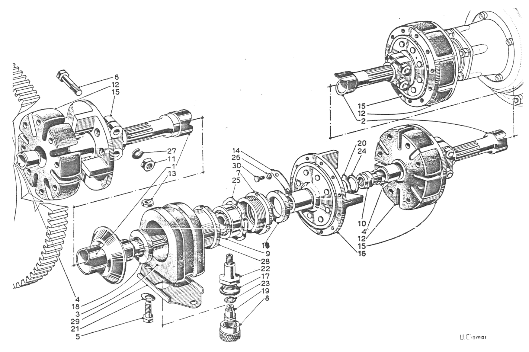
Tav. 36 SII - Propeller Shaft for 4th Series Types
• The unit is similar to that fitted to the B10 and B12 cars. See above for servicing details.
• A 2-piece prop-shaft with a centre bearing and anti-vibrator. See Tav. 36 above for the B20 4th series. The parts for the B24 are identical except that the rear shaft (2), and the greaser for the Spider America model (21) are different
• Rubber spiders (14) are the same as B10 etc. Broken or split spiders will cause vibration. Fitting the spiders into the alloy housings with talc can help disassembly.
• Rubber anti-vibrator (5) is larger than B20 3rd series
• Spacers (15, 29) for adjusting the float of the centre anti-vibrator were fitted by the factory in 0.5, 1.0 and 2.0 mm thick sizes.
• Rubber stopper (35) is special to this group of models
• Centre bearing (12) is RIV 5 BB, dimensions 52 mm o/d, 20 mm id and 21 mm wide
• Counter weights (9) as fitted by the factory were of lead 1 mm or 2 mm thick with locking weights (16) of 0.5, 0.8 or 0.9 mm thick.
• (20) are rubber seals
• Washer (23) changed at cars B20-3656 and B20S-1015 from a lock washer to a plain washer, but applies to preceding vehicles.
• (11) is a knurled alloy cover for the greaser, with fibre washer (19), vital for its security.
• (32) is a bronze bush in each of the three couplings, which provides accurate centring of the coupling flanges. Wear in this part will cause vibration.
B20, B20S & B24S Convertible 5th & 6th Series
The cross section applies to cars from & including B20-3697, B20S-1256 & B24S-1182
Servicing and description is similar to the previous models described above, but an entirely new and more conventional shaft and coupling was used. See Tav. 36 bis below.
- Rubber anti-vibrator (36 bis #3) is the same as the 4th series. Its retainer (36 bis #18) is bolted to floor. Spacers (36 bis #26) come in different thicknesses
- Centre bearing (36 bis #11) is also the same as RIV 5 BB.
- Rubber seals (36 bis #22) are important to protect bronze bushings (36 bis #4).
- Greaser (36 bis #19) is the more modern ball & socket type. No cover is provided as on earlier cars.
- In the late type of prop-shaft there are three bolt sizes: 65, 71 and 76 mm long. There are six 65 mm bolts (36 bis #6). There are nine 71 mm bolts (36 bis #7). The three 76 mm bolts (36 bis #5) hold the first joint onto the flywheel flange. Careful perusal of the above diagram will indicate which is which.
- However, given that the prop-shaft is a carefully balanced unit, it is essential, on disassembly, to note the punch marks on each bolt and flange and replace exactly on assembly. If the marks are not there or not consistent then make new marks. For example parts 36 bis #6, 13, 14 & 15 – the flanges with nuts & bolts are all punch-marked at assembly
B24 Spider & Convertible

B24 Spider & Convertible 5th & 6th Series (Tav. 36 bis Ref. 6)