
Front Axle
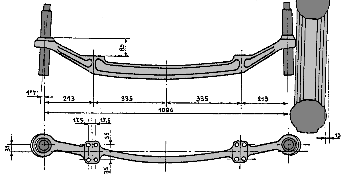
From AST Sketch 283 I 23.3.59
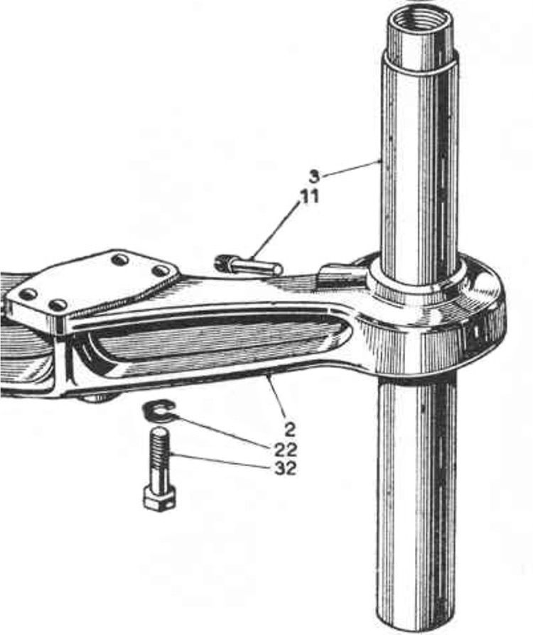
From Series I& Series II Parts Books -Tav49
Part #2 is the axle (assale), #3 is the suspension tube (asta) & #11 is the locating pin (grano)
Notes on Front Axle
- All Aurelia cars had a beam front axle of the same overall dimensions as shown above. The axle is fixed to the car on each side by 4 large bolts locating a rectangular flange onto the boxed beam running each side of the engine compartment.
- Analysis of the Parts books shows the following:
- All cars in the Series I plus the B12 & B20~B24 4th series have axle B10-0601R / 1600389 – see #2 (Axle - B10-73001 / 2127460) & #3 (Tube – B10-73051 / 2127466) in Tav. 49 above.
- In other words the axle beam & bare suspension tube are the same. The suspension components differ between the various models.
- All B20~B24 5th&6th series cars have axle B20-0601R / 1600196 which consists of a new beam 2131015 but the same tube 2127466. The section of the beam was changed to increase stiffness to match the increased weight of the cars & the larger brakes.
- Many owners of earlier B20 cars have attempted to solve brake judder problems by changing to these later axles. The advised solution is to overhaul the brakes properly. In addition the tolerance for the 8 axle locating bolts is very tight & obtaining a good fit for a non-original axle is problematical. The axle was probably fitted individually to each car as they are numbered & noted in the car’s data at the factory.
- The track of the front wheels on all Aurelias is 1280 mm, except on B50, B51, B52, B53 & B15 cars where it is 1300 mm.
- The stub at either end for holding the steering & suspension did vary slightly in detail between models
- Sketch 1059: See diagram below. Please note following conditions for measurement & adjustment:
- Caster: Should be measured with car under static load: Minus 1 degree
- Toe-in: See Steering Arm, Track Rod & Toe-in
Caster, Camber & King-pin Inclination for Aurelias
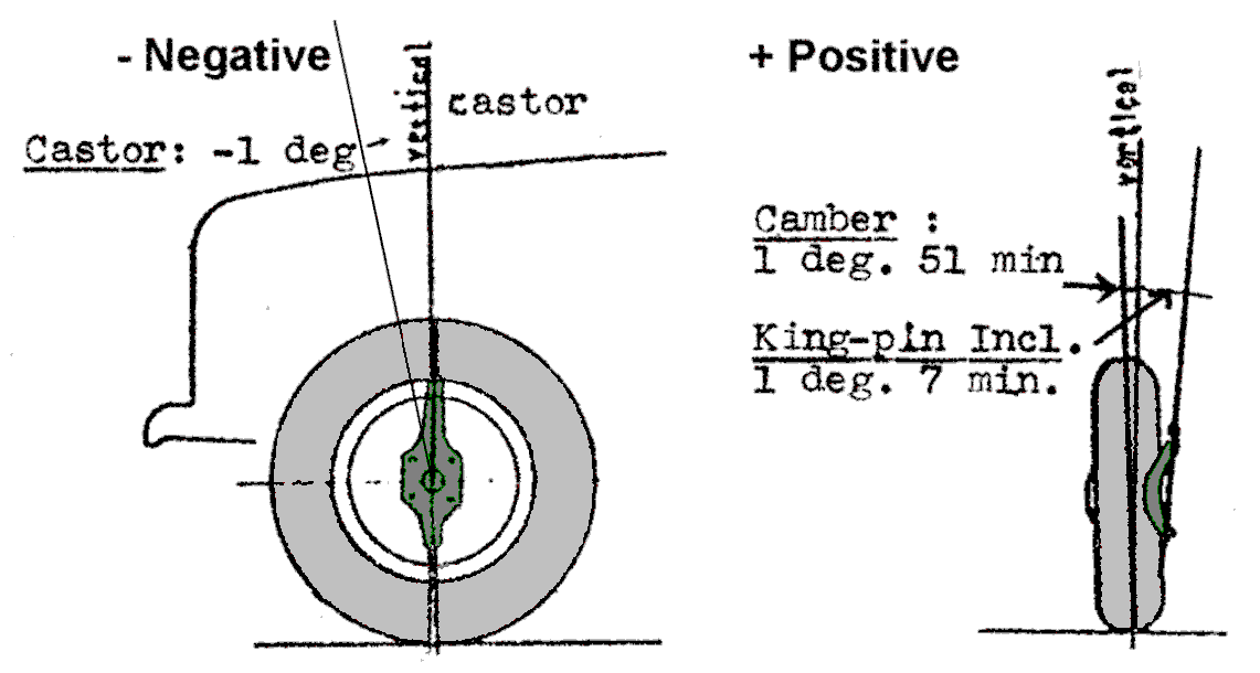
From AST Sketch 1059 I 18.2.59
Aurelia Beam Axles
Article by Marc Bondini from the Australian Lancia Register Newsletter in 2015-6, republished with thanks to the Author and the ALR.
During the restoration of my own B20 and having had to review some old accident damage, I found it necessary to confirm the Aurelia front end geometry.
It could be said that the Aurelia axles were under-rated and, from what I’ve witnessed over the past years, it seems to be true considering the main axle member from the chassis mount to the kingpin was up-graded on the 5th and 6th series cars.
As a reference, I have three Aurelia beam axles, the original, (with damage history), a very clean 3rd series and a B12. I have bolted all three under the car to check which would be best. The result was terrible. The camber and caster, left side and right side, were all different, and there is no way to accurately measure them on the bench. This sent me into a tizz, trying to find references and previous experiences of which I found little. Investigations with suspension engineers and workshops came up with rejection, ‘too-hard’ and OMG from the bewildered under 35 year olds, who had never seen a sliding pillar front suspension. This left me with the thought - I will have to do it myself. So after a day or two reflecting whilst driving the Monash conveyor to Melbourne, I realized a firm reliable datum and strong base was necessary to not only measure, but also to perform the adjustments on the main beam.
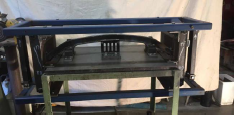
The axle bolted to the mark-up table with the jig frame assembled around it
I have a 75mm thick, ground surface, steel mark-up table, which, coincidently, was the perfect length. A jigging frame was built on top. Once this frame, with square straight lines, was assembled around the axle and sliding pillars, the errors in geometry were very easy to see.
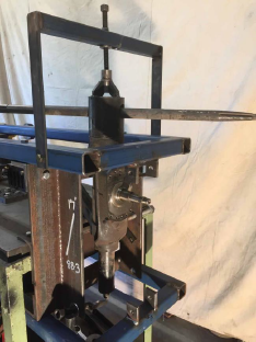
The axle in the jig with the spanner and long bar (T Ford drive shaft, vanadium steel) for undoing the bottom cup
For those who know Aurelias, they are prone to steering shimmy and brake shudder. Over time there has been much conjecture around this topic and now, after twisting my head around it for the past weeks, the following are my thoughts. As the Aurelia brakes are bigger than an American Tank and around 200mm away from the chassis mount, this out-rigger part of the beam is under a huge amount of twisting force. The I-beam cross section of the axle handles the vertical weight of the car and load quite well, but doesn’t handle the rotational braking force. Brake juddering under load adds shock loading to the twisting force on the beam.
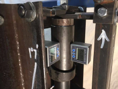
Inclinometers measuring caster (left) and camber (right) in the jig
After having three beams in the jig, most of the vertical pillars were leaning forward which creates a negative caster or reduced trail of the wheel, some as much as 4°. This can only happen by the braking load rotating the top of the pillars forward. The forward and aft vertical location of the pillars doesn’t seem to be affected. A few Aurelias that have been in the workshop have had shims placed under the rear mounting bolts to bring the caster back to the negative 1° specified. The factory specifies negative 1° but shows positive 1° in the drawings.
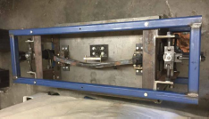
A view of the axle inside the frame form above showing the threaded rods for pulling and pushing the pillars, top and bottom, in the desired direction
So, to rectify the problem, it is necessary to twist the beam axle back to where it should be. Pulling and pushing the forged steel beam back to factory specifications is the only way to achieve satisfactory front end geometry. As tonnes of force are required, and the steel is ductile, soft heat (and a lot of it) is used along with screw adjusters, pulling and pushing in all three planes on the extremities of the pillars. Special tools were machined up to grip the pillars and to protect them from the applied loads. Another very handy device for measurement is the modern digital inclinometer. These are live and read accurately to two decimal places of degree, so during adjustment, very fine control is achieved.
Another topic worth raising, but I should say I’ve never seen, is a broken front axle. For this reason, proper cleaning and crack testing of the beam is essential for safety purposes.
Back to the geometry of the front end. Aurelias seem to have a very small caster angle and it seems to go against the regular adopted principle of a larger caster angle or longer trail for high speed. Aurelias are most comfortable and sure footed at speed. The adoption of Michelin X tyres, which had a strong self centering action compared to cross-ply tyres, possibly contributes to this stability.
According to the factory spec sheets, the chassis mounting plate is angled up to the rear of the car by 1°. I believe the reason for this is passenger and luggage weight in the rear of the car increases the caster and therefore the stability of the car.
An associated topic, which I haven’t fully understood on Aurelias, is the variable wheel shimmy. If it’s a geometry issue of the front end, why is it there sometimes and not others? The only answer I have for this is brake drum balance, wheel balance or Michelin tyre flat spotting. As the cars are often used infrequently and parked in the same spot for extended periods, they flatten and take time to reform. This could explain the scenario, ‘the car is driving beautifully and after the next corner, the wheel shakes at 80kms’. A possible answer is the imbalance at the wheels move in and out of synch and, as there is a direct connection between the two wheels and no rubber bushes to absorb the harmonic wave, it is amplified.
So if you are an Aurelia owner, and you have front end shimmy there is a process of elimination to sort the problem:
- Check the front end geometry. This can be done with a digital inclinometer, the old Repco front suspension measuring set or have it checked on a modern laser system that many tyre dealers use.
- Balance the wheels and tyres; select the best for the front. If possible, and you have the original wheel weight studs, get the wheels onto a modern computerised balancing machine which can locate the stud positions, specify the stud locations as spokes and the system will automatically allocate the weights over the appropriate stud.
- Have the brake drums balanced. I have seen them up to 8 grams out over the 300mm diameter, which is significant.
- Have the drums checked for hot spotting and out-of-round.
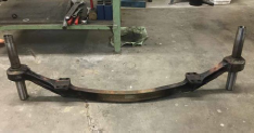
The straightened axle. Note the ‘heat’ marks
Unlike the lovely vernier cam timing adjuster and its infinite adjustment, Lancia, in the Aurelia model, has no camber and caster adjustment, making it difficult to fine tune. The Appia, with its lighter weight and braking, does not seem to have the same problem. Perhaps it is the heavier brakes, and the sporting prowess of the Aurelia (being used likewise in the sixties), that caused the beam axles to twist, leaving us with the problem fifty years later.
A couple of the members failed the crack testing and required repairs. Two types of imperfections were seen. The first was a fold in the metal during the forging process along the ‘I’ beam webbing. In one of these the imperfection ran approximately 150mm along the beam. This type of crease would have been on and a part of the car since new and is not a concern.
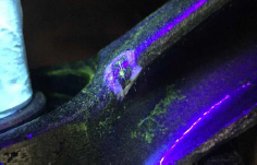
The fatigue crack to be welded
The second type, a fatigue crack, is of concern. In this case a crack was seen in the most stressed area of the beam. I believe it occurs with the added load of bounce, braking and corner compression, exacerbated by brake judder. In both cases the crack occurred on the top edge of the webbing which bolsters the king-pin.
The repair entailed jigging the beam, setting the geometry and TIG welding the crack.
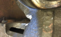
The crack has been ground out
The crack is first grooved to the root of the imperfection, the beam heated to a dull red to reduce localised stress and the crack is TIG welded with a ductile wire.
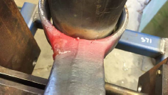
The welded up crack
It is a two-person procedure as the gas heating is continued during the electric welding and left on after the welding to de-stress and anneal the metal. The beams are a large section of metal and cooling back to room temperature takes about five hours!
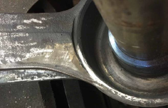
The finished weld
After cooling the axle geometry was found to be undisturbed and correct. Further crack testing gave the all clear.