General Specifications & Description
The following diagrams show the general arrangements for the various models
B10, B15 and B21 – S1 Tav. 23
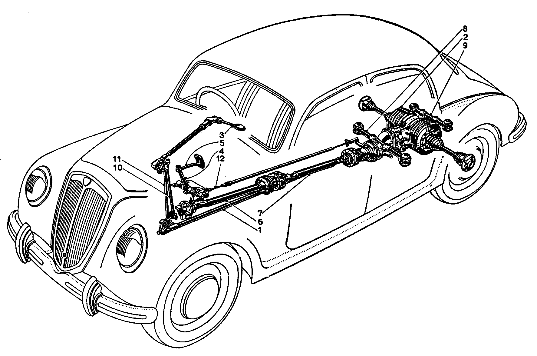
For both systems it was noted that the B20/B20 was available with a floor-mounted gear change lever
B12 & B22 – SII Tav. 24
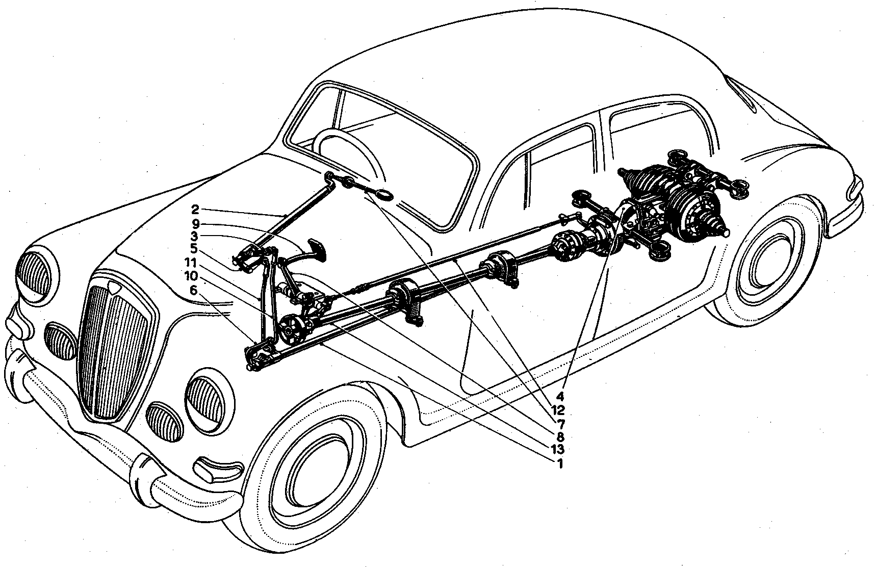
General Arrangement of B20 1st, 2nd & 3rd Series Propulsion Unit
B20-1001 to B120-2951
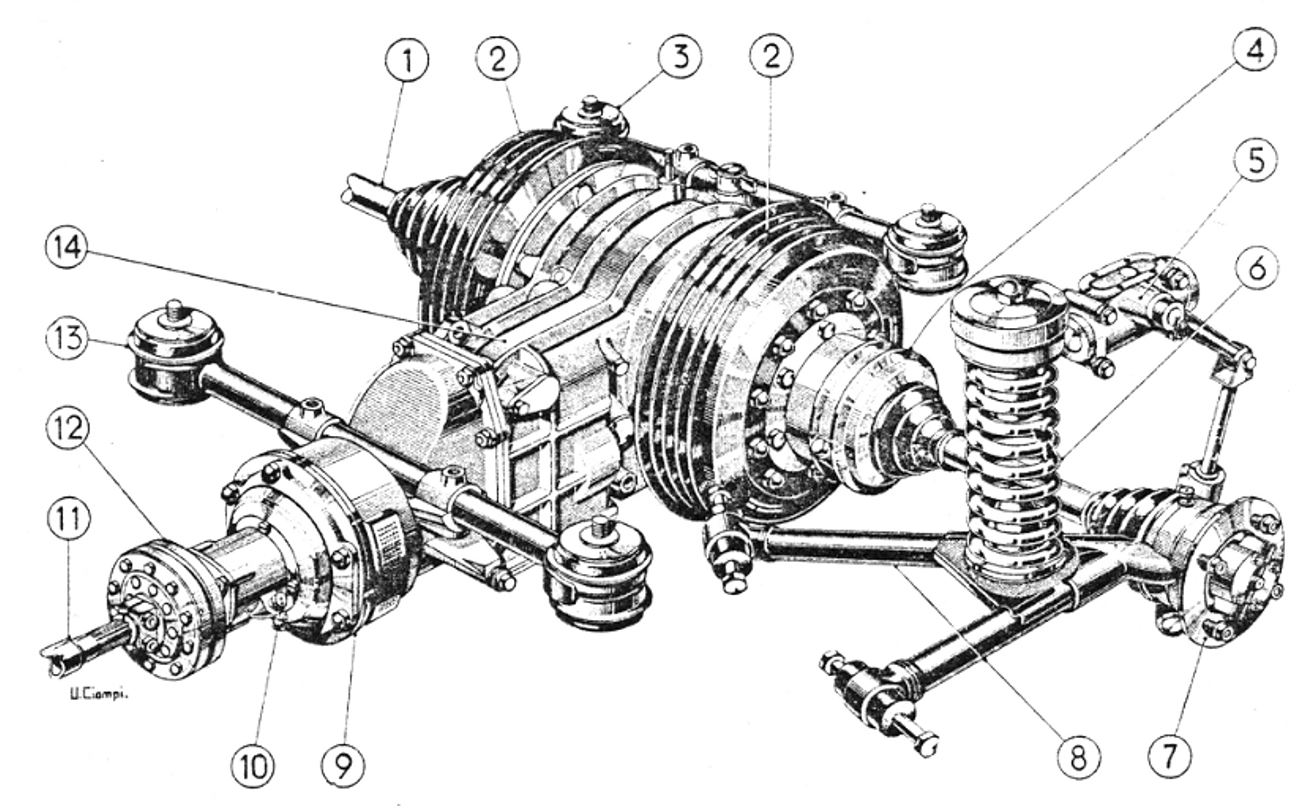
This is the famous coil spring and wishbone rear suspension of the ‘Series I’ cars and of course of the B20s, which made such a competitive impact from 1951 to 1953
List of Parts
- Rear wheel drive shaft
- Rear brake drums
- Rubber mountings of propelling unit to body shell floor
- Drive shaft joint housing
- Lever-arm dampers
- Rear suspension coil spring
- Wheel hub containing drive shaft outer joint
- Rear suspension ‘wishbone’
- Clutch housing
- Greasing point for clutch shaft
- Propeller shaft – rear section
- Propeller shaft joint – rubber spider type with alloy housings
- Rubber mountings of propelling unit to body shell floor
- Gearbox
B12 & B20 4th Series Coupe Transmission General Arrangement with cable operated clutch
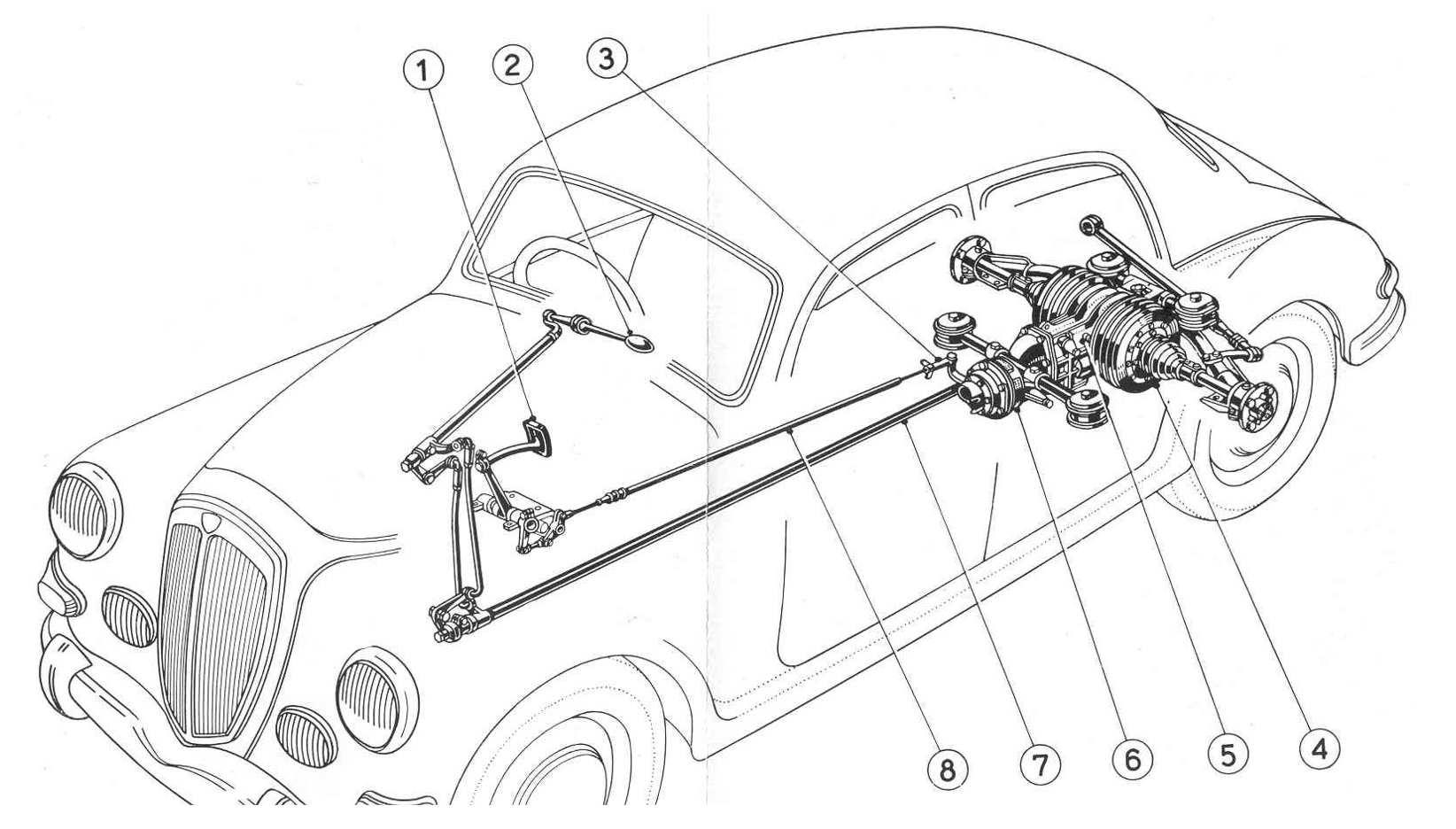
List of Parts
- Clutch pedal
- Gear shift
- Clutch pedal adjusting nut
- Rear brakes drum
- Gearbox & differential unit
- Clutch
- Gear shift control shaft
- Clutch control
B12 & B20 4th Series Coupe Transmission General Arrangement with cable operated clutch
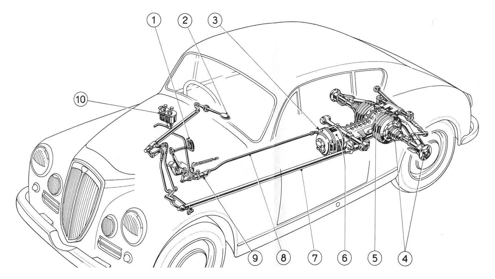
List of Parts
- Clutch pedal
- Gear shift lever
- Hydraulic cylinder adjustable fork
- Joints
- Propelling Unit
- Clutch
- Gear shift control shaft
- Clutch control piping
- Clutch hydraulic control pump
- Clutch & brake oil feeding tank
B24 5th & 6th Series Convertible Transmission General Arrangement with hydraulic clutch
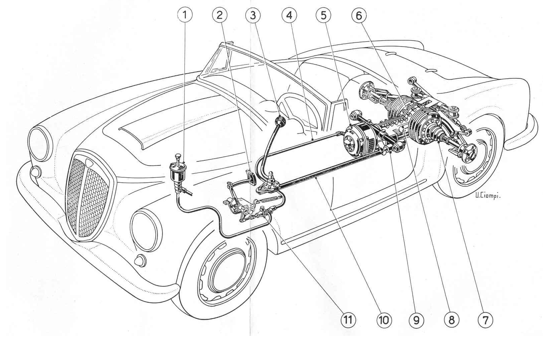
List of Parts
- Clutch & brake oil feeding tank
- Clutch pedal
- Gear shift lever
- Clutch control piping
- Clutch
- Propelling Unit
- Joints
- Gearbox
- Gear shift control box
- Gear shift control shaft
- Clutch hydraulic control pump
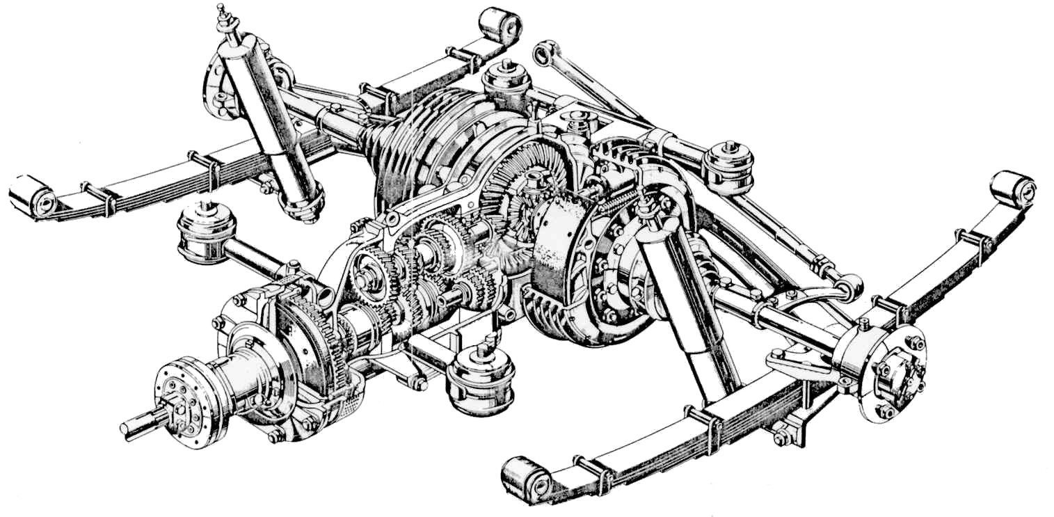
Sectioned view of B12 Rear End: Similar to all other Series II models with De Dion rear axle