Engine Mountings, Engine Removal & Replacement & General Guide To Reassembly
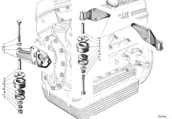
ENGINE MOUNTINGS - See Tav. 9
The right-hand front mounting is a casting fitted to the block with a gasket. The left-hand front mounting is in the dynamo support. The bolts are the same but different from the rear mounting bolts.
The rear engine supports are identical, or should be. If they are not or have been reversed it is a sign of possible distortion of the engine bay due to front-end damage.
All four mountings are otherwise identical consisting of the same rubber and metal parts (#6,8,13,3,12,9,11 - Tav. 9).
Large rubber (#13), part no. 2125808 is the same as found on the engine supports of Lancia Fulvia and "2000" cars. Small rubber (#12), part no. 2125806 seems to be unique to Aurelias
Tav. 9 Engine Mountings
Engine Removal & Replacement
Engine removal is relatively simple providing block & tackle are available for lifting 5-10 cwt. Remove the bonnet preferably using two people to avoid damaging the paintwork. Disconnect the battery.
Having detached the propeller shaft from the flywheel, disconnect the radiator hoses top and bottom and remove the radiator by removing nuts from mountings at bottom. This will avoid damage to the radiator core. Disconnect fuel line, exhaust down-pipes from manifold flanges, electrics to dynamo, distributor, starter, water temperature gauge, oil pressure gauge line and throttle linkage.
Remove engine mounting bolts - see Tav. 9. It is wise to remove or protect the brake/suspension fluid reservoirs as this unit is easily damaged during the removal.
Lift the engine (approx. 3 cwt.) and roll the car/engine away. Rest the engine on blocks of wood, whether on the bench or ground, to avoid sitting the engine on its protruding sump plug. Ideally an engine stand should be used.
Removal is the reverse of the above.
General Guide To Reassembly
Refer to the respective sections within '1.0 Engine' for details of the various sub-assemblies and systems. The following notes refer specifically to the 2.5 litre B20 engine and will vary slightly for the other Aurelia engines.
- Fit the 4 main bearings into the caps in the crankcase. All are different sizes, so check carefully.
- The thrust washers fit round No. 3 journals, milled slots face outwards towards the crank web.
- Sit the crank with pre-lubricated journals into the shells and fit caps with shells.
- Check that the oil blanking plate behind the flywheel is screwed in.
- Fit tab washers and nuts to the main bearing bolts, noting odd shaped washers on the rear main bearing cap. Tighten main bearings to 40 ft.lbs. or 54.2 N.m
- The oil pump cannot be fitted until the rear main bearing nuts are tight.
- Assemble pistons onto connecting rods, making sure that the pistons are inserted in the bores the right way round, with the chamfers facing towards the centre of the block.
- Insert piston and rod, without bearing cap, into the cylinder bores from the top of the block, having compressed the well-oiled rings with a ring compressor and tap the piston into the bore. Rotate the crank so that the big end slides between the crank webs with the journal being positioned farthermost away from the bore.
- Fit shells, lubricate, fit cap and tab washers and tighten bolts to 28 ft.lbs. or 38 N.m
- Repeat for the other 5 bearings/rods/pistons, rotating the crankshaft frequently to check for any excessive tightness.
- Fit timing chain. The tensioner sprocket has to go on before the crank sprocket is fitted. Do not fit the dowel pin into the camshaft until the camshaft timing is being done
- Check that the engine support next to the chain tensioner is tight and that the joint is oil-tight as this is pressurised when the engine is running and is difficult to remedy later in situ.
- Fit oil pump to rear main bearing cap (no gasket) and prime the pump with oil. Assemble the pick-up pipe and filter.
- Fit the sump (no gasket) and remember the long ‘steady’ stud with copper washer, which bolts through the bottom of the sump into the rear main bearing.
- Fit the oil filter base plate, leaving the filter until last, priming the filter container with oil before bolting up.
- The timing cover cannot be fitted until the camshaft is timed. To do this, one cylinder head complete with valve gear must be bolted down in position on the block.
- Fit the flywheel, noting that the ‘0’ marks on the exterior flanges must line up, otherwise the TDC (top, dead centre) mark on the starter teeth will not indicate TDC for No. 1 cylinder. Tighten flywheel bolts to 40 ft.lbs or 54.2 N.m. and lock with tab washers.
- Fit flywheel cover and prop-shaft coupling flange.
- Remember to insert cam followers into block before fitting the cylinder heads and to fit oil pump/distributor drive shaft.
- Fit petrol pump and spacer using special tubular bolts.
- Assuming the cylinder head has been checked and overhauled, grind in the valves, fit springs & cotters; check that the steel seating rings under the springs are in position before assembly.
- Fit inlet manifold with gasket; bolt up securely as this must be watertight.
- Fit cylinder head gaskets and heads following tightening sequence - see Cylinder Heads & Rocker Covers.
- Fit rocker assemblies.
- Time the camshaft (Valve Gear) and fit timing cover and gasket using 10 mm half-nuts.
- Remember oil-thrower on the crank sprocket.
- Fit fan pulley and starting handle dog.
- Bolt on exhaust manifolds with gaskets.
- Fit carburettor inlet heating manifold across inlet manifolds using gasket cement to ensure water tight seal, one the cylinder heads have been fully tightened (NB cylinder heads will need to be re-tightened several times when using copper asbestos gaskets (Cylinder Heads & Rocker Covers).
- Fit rocker covers.
- Fit spark plug leads noting that the numbers stamped on the cylinder heads by the plugholes correspond to the numbers on the distributor cap. Set ignition timing. See Starting & Ignition System.
See
Tightening & Torque Data for torque settings