Dynamo & Voltage Regulator
The following dynamos were fitted to Aurelias
| Aurelia Model | Lancia Part No. | Manufacturer Part No. |
|---|---|---|
| B10, B50 to 53 B20 Series 1 & 2 up to 2231 B15, B21 | B10-6100 See Tav.57 #68 & Tav.57bis #78 | Dynamo: Marelli DN 22 A 200/12/1700 D Regulator: Marelli DN 2/60 A |
| From B20-2232 B22 B12 B24 | B22-6100A, later 82129746 See Tav.58 #14 Z20-6144, later 82103714 See Tav.58 #29 | Dynamo: Marelli DN 22 C 200/12/1700 D Regulator: Marelli IR 15A 200/12 The original Marelli regulator may be replaced by Lucas Model RB106 (John Savage 2008) |
| Notes: |
|---|
| Information taken from Lancia Aurelia part catalogues. Series I, Tav.57 & 57bis part #3 & Series II Tav.58 part #4. See also 'General Data & Specifications' and 'Electrical System General Description' |
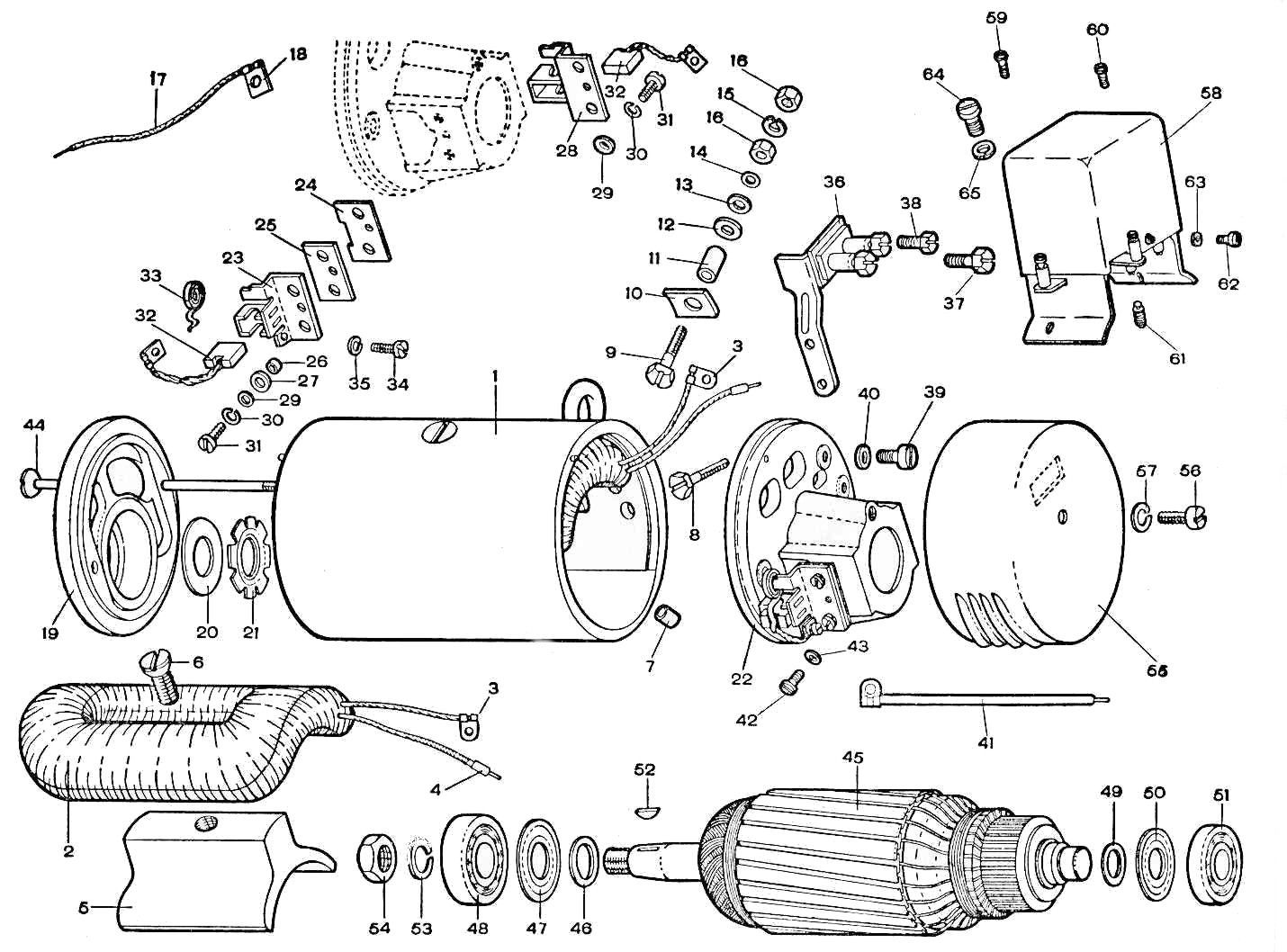
| Rear bearing is RIV 2065B or SKF EN15 or 393065 (Australia New Departure G7109), dimensions 15 mm id, 35 mm od, 8 mm width. Lancia part no. B10-6100/22, later 82190084 |
| Front bearing is RIV/SKF 6203 or RIV 01A, dimensions 17 mm id, 40 mm od, width 12 mm. Lancia part no. B10-6100/21, later 82109083, 82048043 |
| Extractor for belt pulley on dynamo possible with Fiat tractor nut tool part no. 1216411 |
Some notes on the Aurelia Marelli Dynamo & Voltage Regulator by John Savage with additions from Paul Mayo
1. After trouble with these items it is wise to fit an Ammeter either temporarily or permanently as this will give warning of future problems & help in setting up the voltage regulator.
2. Use an ammeter with at least 20 Amps at full scale, connected in series with the wire which runs between the starter motor terminal (the same terminal as the heavy battery cable is connected to) & the fuse board lead marked ‘30’ connecting it to the bulkhead side of the spot-lamp/cigar lighter fuse. If the meter reads in reverse, swap the leads at the ammeter terminals.
3. The Marelli dynamo is rated at 200 Watts & should not be allowed to deliver more than 18 Amps continuously. The brushes have a minimum operating length of ½” (12 mm) & a suitable replacement is made by Bosch for the Volkswagen Beetle, & thus readily available.
4. The rear bearing can fall apart with age & can break up & damage or seize the dynamo armature. Always replace the dust cover on the rear of the dynamo to keep dirt out of this bearing. Make sure that the brush ‘pig-tails’ do not short out on the inside of the cover.
5. The Marelli voltage regulator can be replaced by a Lucas 5-terminal unit such as the RF95A or the RB106A, as fitted to the Mini, Minor 1000, Hillman Minx etc. To install a Lucas unit proceed as follows:
Disconnect the battery leads. Make an L-shaped metal bracket so that the regulator bolts to the vertical side of the ‘L’ & the foot of the ‘L’ uses the original regulator mounting holes on the side of the engine bulkhead. Connect as follows:
i. ‘E’ on the Lucas regulator to an earth wire under a regulator mounting bolt.
ii. ‘D’ to ‘D+’ on the dynamo, also wire 61 to ignition light.
iii. ‘F’ to ‘F’ on dynamo
iv. ‘A’ to wire 51
If there is not enough compensation when all the lights etc. are on, then wire 51 should be connected to the A1 terminal.
Before attempting to adjust the regulator, make sure that the fan belt is tight & not slipping. Never move the regulator adjusting screw more than ¼ turn at a time, as this adjustment is very critical, & ideally should be set up with an accurate voltmeter following Lucas instructions.
A rough guide of normal charge rates with a battery in good condition is 10-15 Amps after a cold start tapering down to 5-8 Amps after 10 minutes of steady running.
Dynamo & Belt Adjustment
The Marelli dynamo D22 is rather special in that the axis of the armature is placed off-centre in relation to the outside casing of the dynamo. The photos below illustrate this:

This design allows for a very easy adjustment of the belt, which turns the dynamo & fan. The configuration can be seen in the photo below:
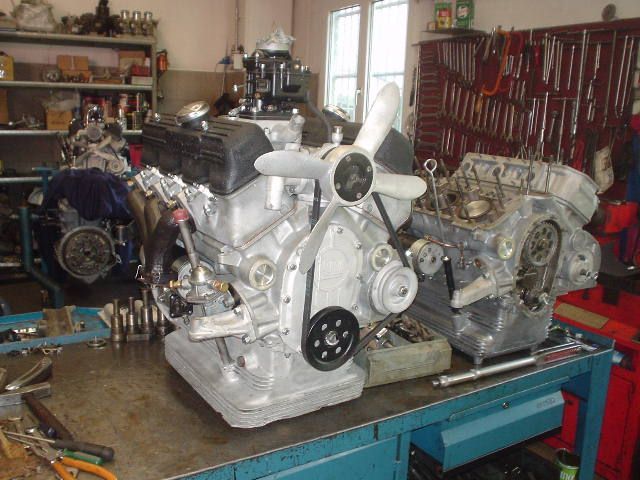
To adjust the tension of the belt, the 17 mm adjusting/locking screw is loosened & the dynamo is turned in its casing to achieve the correct tightness – about 10 - 15mm deflection on the longest section of the belt. Over-tightening the belt will cause problems in the bearings of the dynamo & water pump.

To remove the dynamo from the engine, first undo the pulley-locking nut & washer, & then loosen the 17 mm adjusting/locking bolt holding the dynamo in its engine casing. Rotate the dynamo & remove the fan belt & disconnect the electrical wires. Tighten the locking bolt again to allow the pulley to be removed from its tapered shaft using two levers from under the car – gently as the pulley can break! Take care not to lose the Woodruff key. Loosen the locking bolt again & withdraw the dynamo from under the car.


