Brake Drums
Front Brake Drums
Series I

From SI-Tav. 42 Ref. 7
Series II Except B20 & B24 Series 5 & 6
From SII-Tav. 42 Ref. 6
Front Brake Drum Specifications


Removal of Front Drums
Refer to
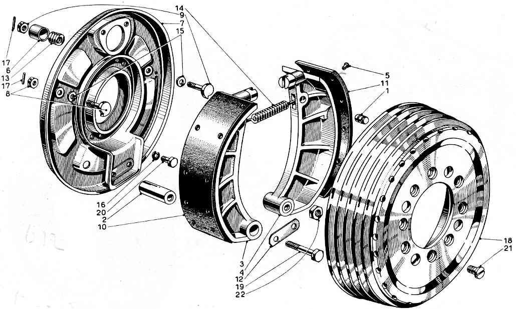
Hubs & Wheel Bearings on hub removal. Note that screws 20 or 21 holding the drum to the hub are torqued to 20.25 ft.lbs. or 27.5 N.m. (Tool 8091142).
Reconditioning of Front Drums - Braking Problems and 'Judder'
Refer also to Wheel Data and Modifications on wheel balancing. John Savage (1977) contributed the following:
Brake Judder is one of the major problems with B20s, especially 1st to 4th series cars. The 5th & 6th series, with a more robust front axle, suffer less from judder. The later axles may be fitted to earlier cars with satisfactory results along with the later brakes and suspension units.
If the later brakes are retained, later J-rim wheels must be fitted. The earlier rolled rim wheels will not accommodate the wide brake drums of 5th & 6th series cars.
One method used to alleviate brake judder was to fit graphite pads, cut from a cylindrical graphite stick, into holes cut into the brake linings.
The brakes usually work better when hot, and can often be fierce and unpredictable when cold.
Different lining materials from those originally fitted may be a judder factor.
Some owners have tried varying the chamfer angle on the leading edges of the linings or even fitting less than the full length of lining, which could of course reduce lining lifetimes from an expected 50,000 miles of normal use.
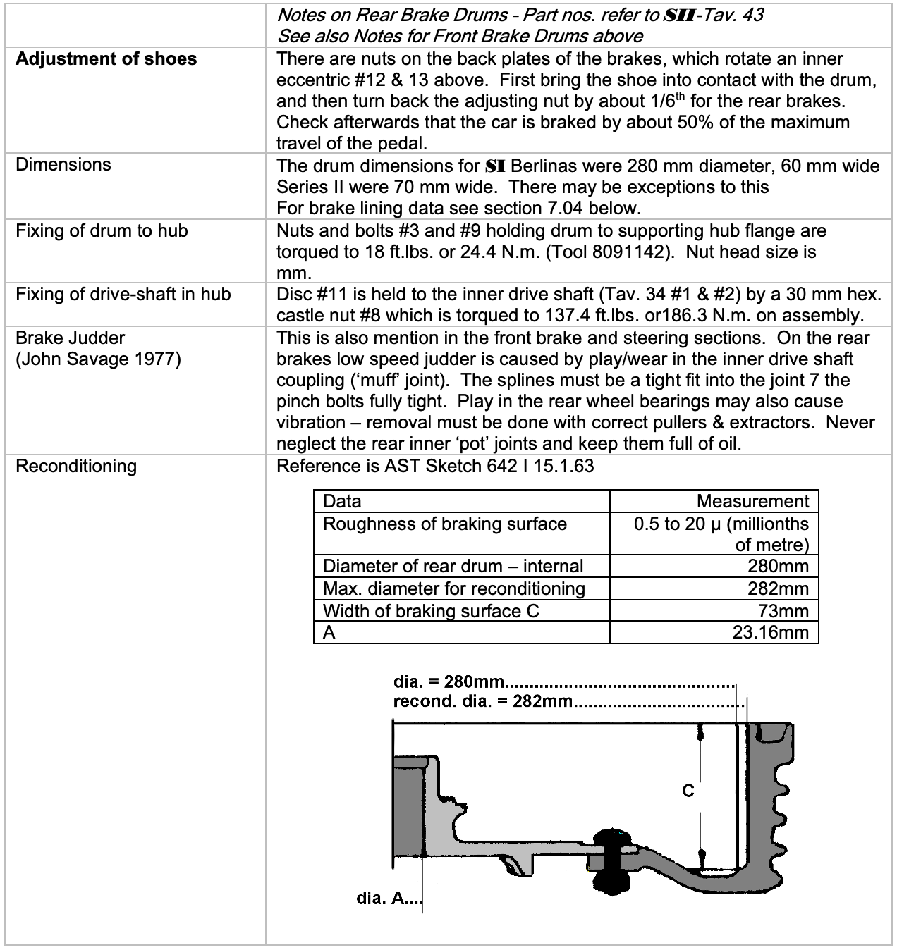
It is likely that a major source of problems in braking and steering efficiency is due to unbalanced brake drums and worn parts in the front steering and suspension. Reconditioned drums must really be re-balanced both off and on the car to ensure smooth running. It is very important that such large brake drums are reconditioned precisely round the centre of rotation and not eccentrically. There is little tolerance (2 mm) for 'skimming' the drums before they become non-functional. They should not be turned in a lathe, but ground by turning around a mandrel fitted to the hub so that a truly concentric result is obtained. The result should be a surface of great smoothness as the specification shows.
Rear Brake Drums
Rear Brake Drums
Series I

From SI-Rav. 43 Ref. 7
Series II

Removal of Rear Brake Drums & Overhaul of Brakes & Oil Seals (Ref. 11)
The following instructions were obtained from working on a B20, leaving the complete gearbox-transmission unit on the car. It may easier to remove the entire unit from the car.
- Undo two 17 mm bolts in the half shaft joint and slide the splined shaft joint towards the wheel. If tight, use a hammer and drift with releasing fluid, but keep the hammer away from the splines.
- Flatten the tab washers and undo six 10 mm bolts around the pot-joint flange (page 02.7, parts 16 & 29). Support the pot-joint when removing the last bolts otherwise it will fall off. Also be prepared for the release of a pint of oil inside the pot-joint. Some of the joints have a metal sealing ring on the flange inner face.
- Clean the central part of the brake drum mounting flange and remove the split pin from the central 30 mm hexagonal castle nut (page 02.6/30 Tavs. 34 & 35, parts 21 & 8). With the hand brake on, undo the 30 mm nut with a ring spanner or socket, preferably hex-sided rather than a bihex or 12-point socket. The nut is torqued to 137.4 ft.lbs. or 186.3 N.m. (reassemble with Tool 8091149) and is likely to be very tight to remove. Release the hand brake and fully back off the brake adjusters.
- By working the drum 15 degrees from side to side and pulling, it should slide outwards. Clearance between the drum and the boot floor support rib, and with the exhaust silencers, may be very tight. Release the exhaust hangers if necessary. Details here will vary between coil-sprung and De Dion cars. Do not do it too vigorously for fear of dropping the brake drum - this could be dangerous.
- Brake shoes are now revealed. They turn about 2 spigots at the bottom of the back plate, and are held on with a tab washer and 2 bolts screwed into the ends of the spigots. Remove these & then tap out one of the spring securing pins. The shoes are then free to come off. Keep parts from each side separate in different containers.
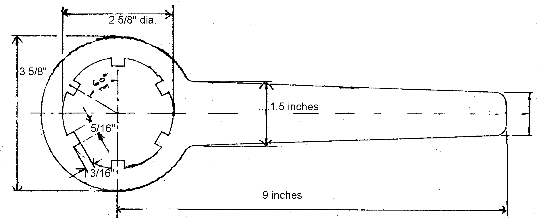
- Leave hydraulic seals in place until a thorough inspection has been done for any leaks. If the transaxle oil seals are leaking oil may well have ‘got round’ the oil thrower & contaminated the brakes. The oil seal needs to be removed with a ‘C’ spanner or a tool as shown below. Do not try to bash the deal out – it will only cause damage. The housings are threaded left-handed on the left side of the car (facing forward) and vice versa. Plug the drive-shaft exits with rag and thoroughly clean the surrounding area checking tightness of nuts and bolts.
- Clean out hydraulic brake cylinders, polish, clean piston and replace seals as necessary. Do not get mineral oil or grease onto the seals or the brake linings – protect if possible with self-adhesive material
- Assemble the 2 shoes over the spigots & slide on about 15 mm. Fit the spring & slide the front shoe home, having located the handbrake control. Use a lever to open the second shoe against the spring & tap home on its spigot. Expand the shoes again with a lever & locate the handbrake control bar between the two shoes.
- Clean any grease from braking surfaces with trichloroethylene or other degreasant.
- Finish reassembly