Starting & Ignition System
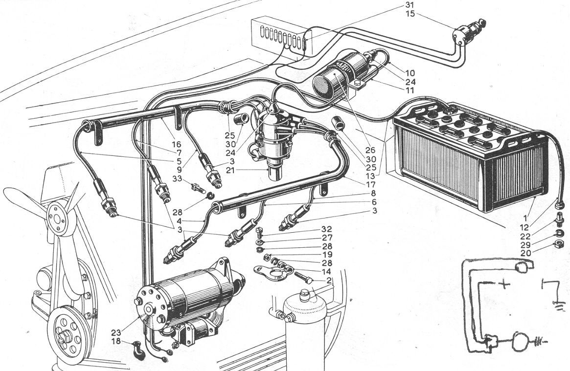
Series I Layout for Starting & Ignition
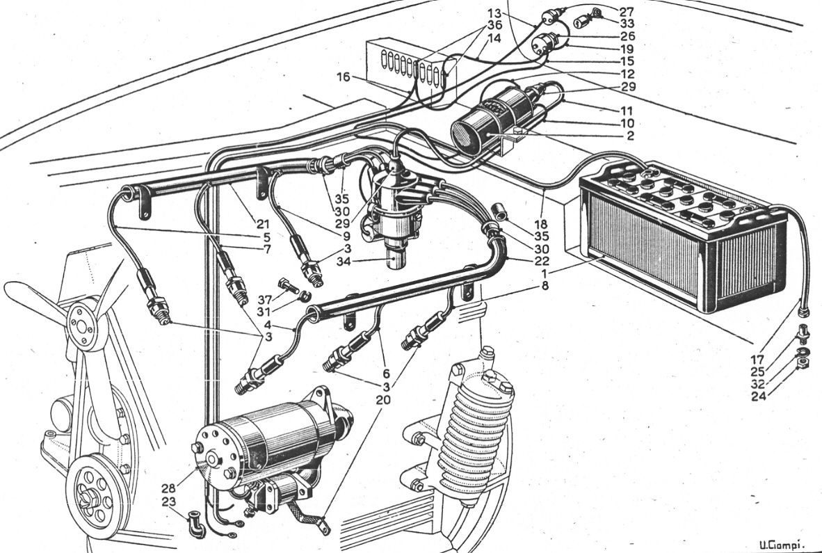
Series II Layout for Starting & Ignition
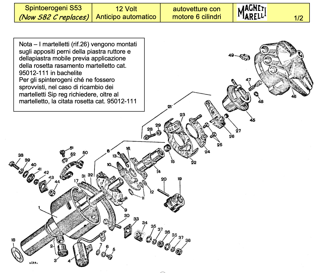
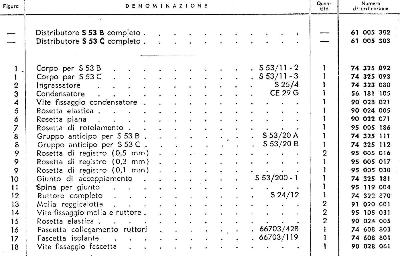
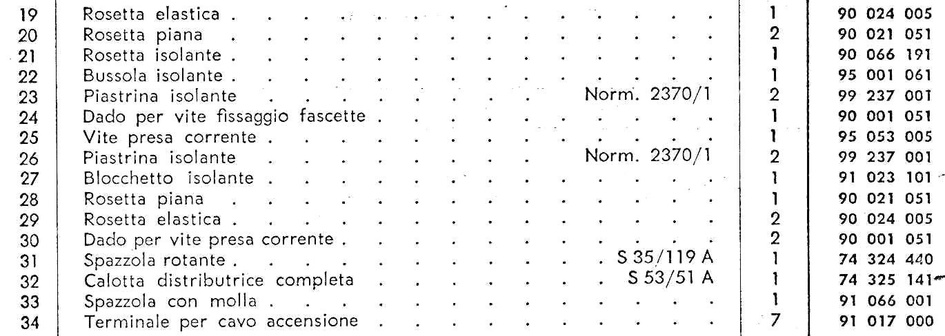
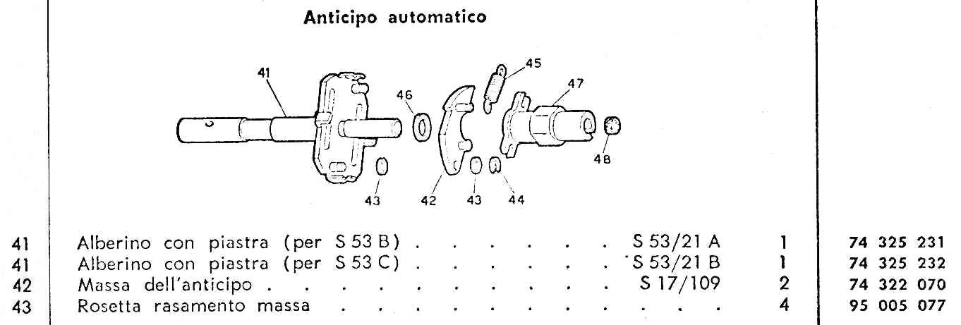
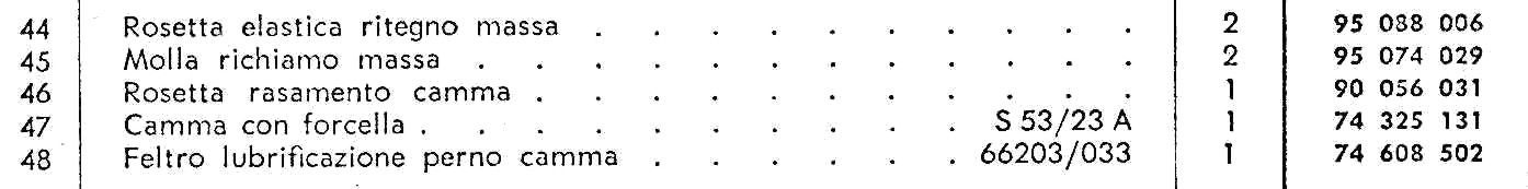
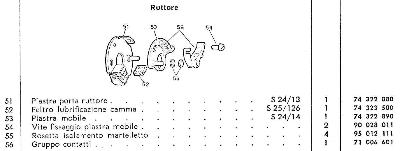
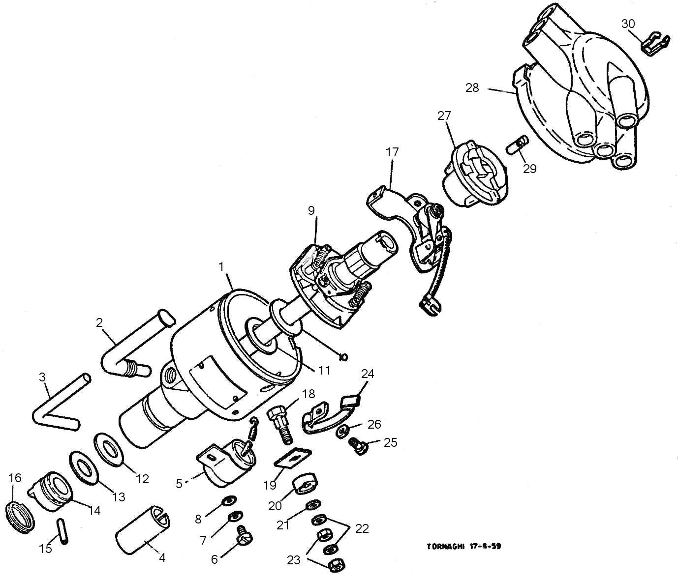
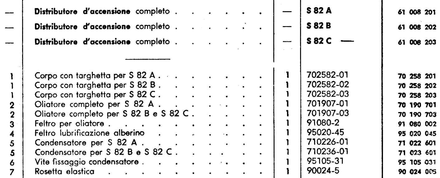
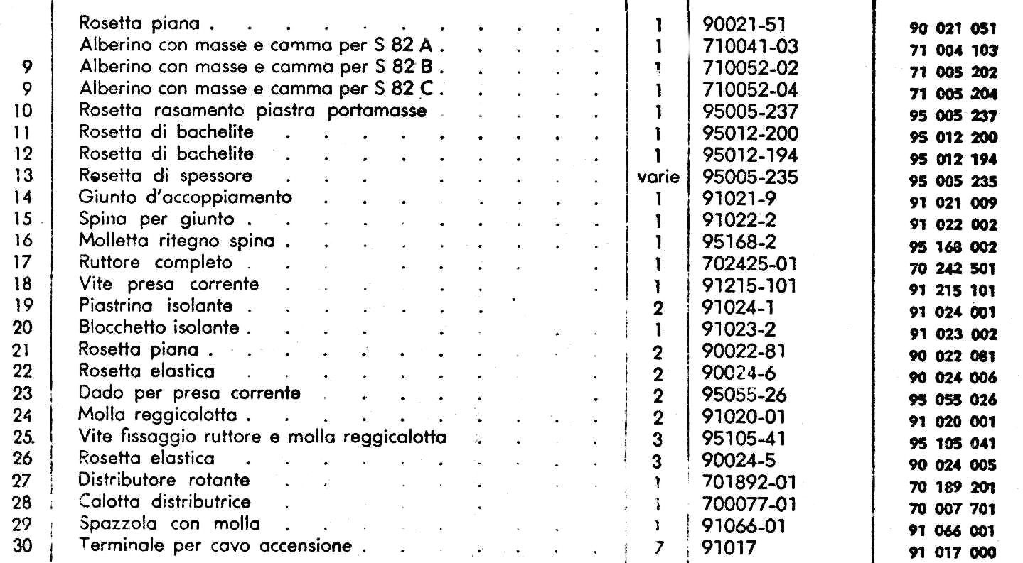
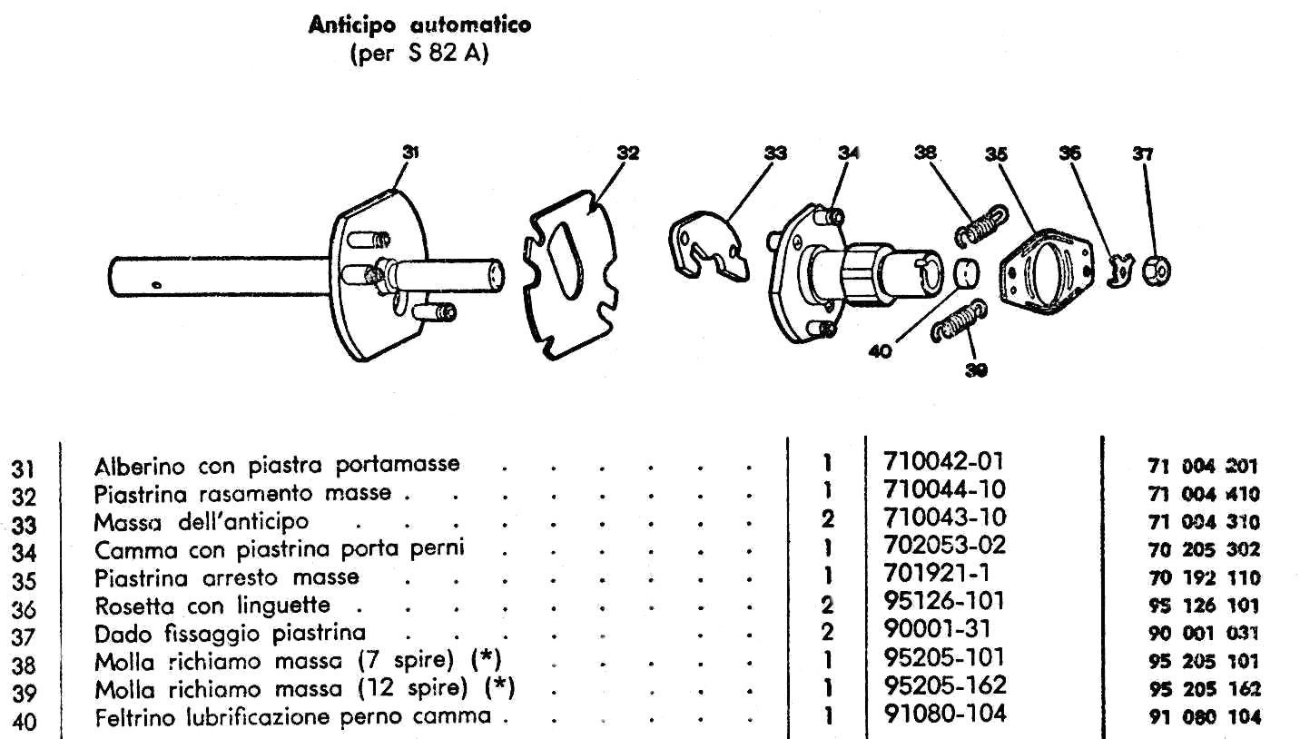
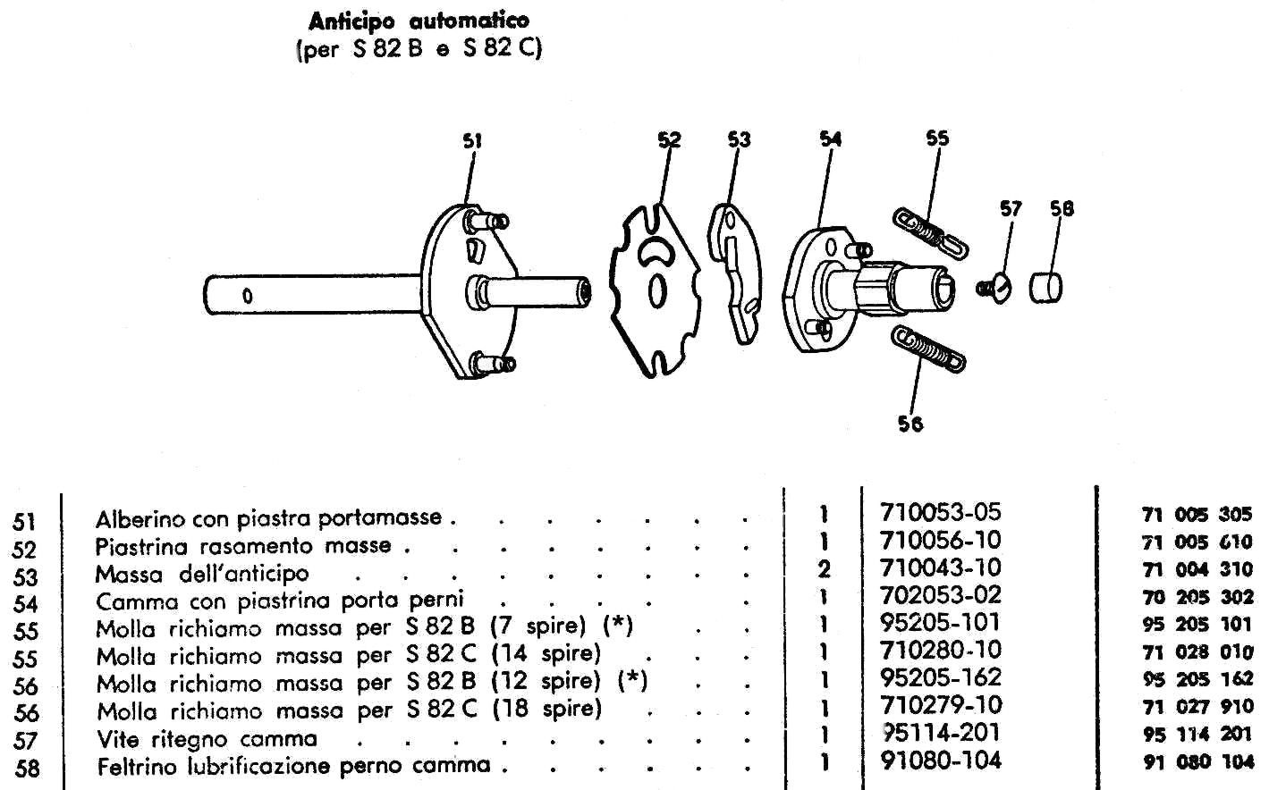
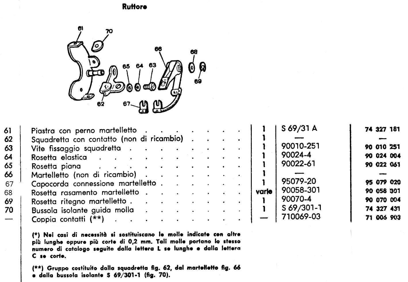
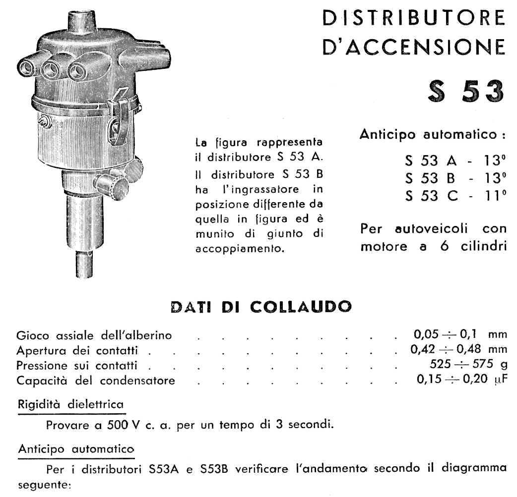
Distributor
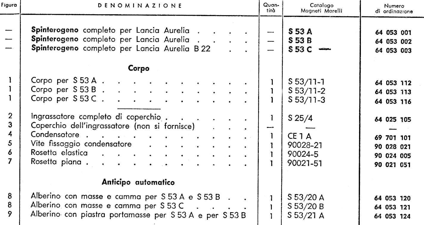
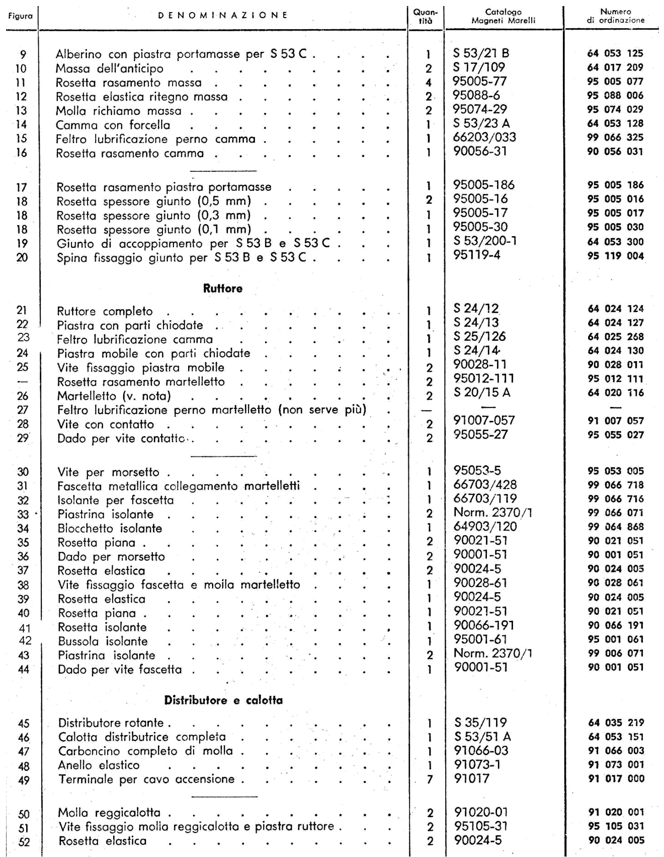
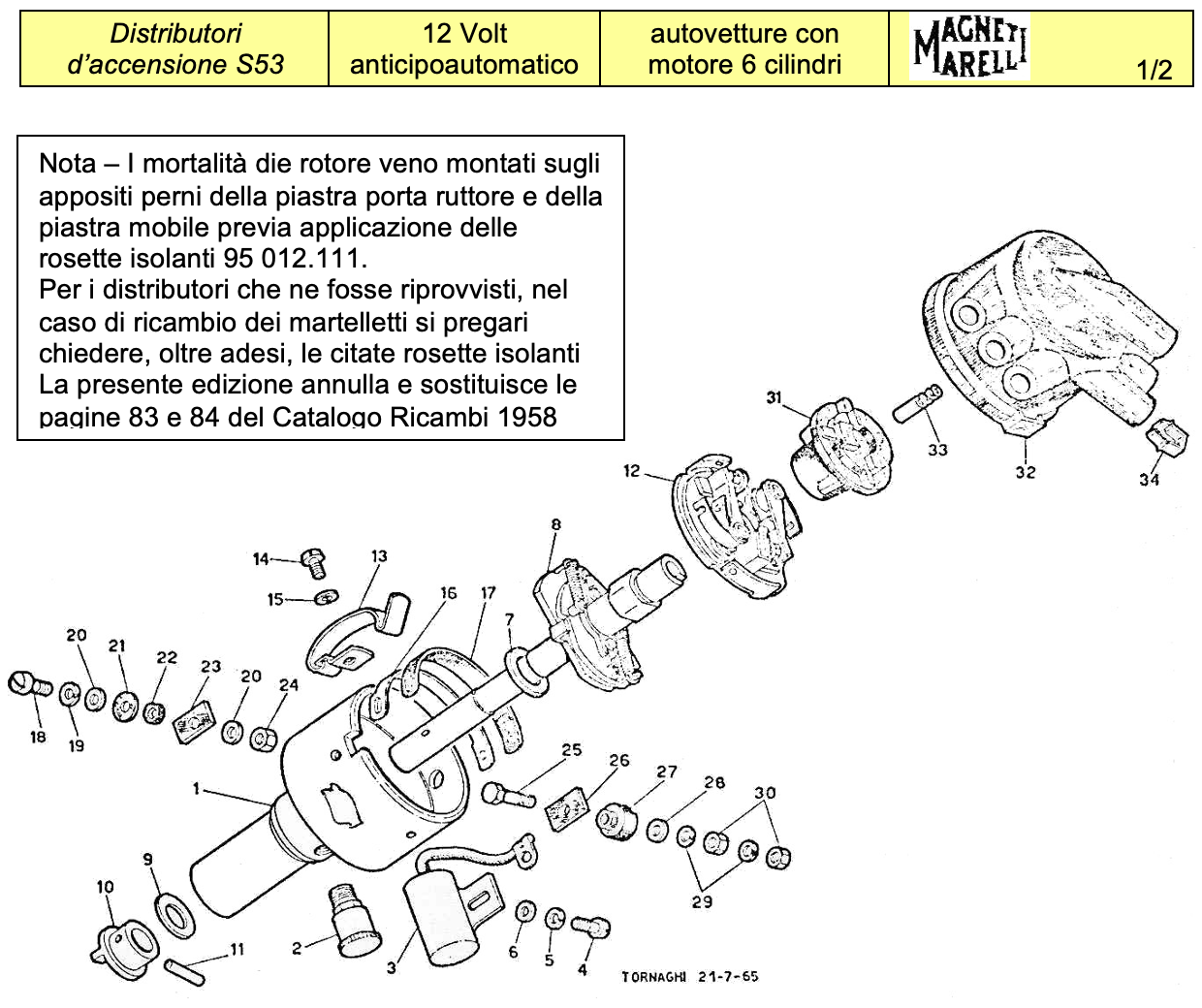
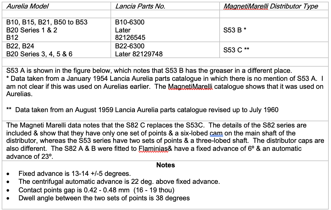
MagnetiMarelli distributors were fitted to Lancia Aurelias. Type 53 was fitted initially but from 1958 Type 82 was available as a replacement (see Table below for more information). Each type was produced in 3 versions: A, B & C.
The following pages are from original 1970’s MagnetiMarelli parts catalogues. I’ve included two versions of the Type 53 catalogues as they differ somewhat & particularly in the part numbers.
According to the Lancia spare parts catalogues the types of distributor fitted to Lancia models was as follows:
Dwell angle
Those owners who have at some time dismantled the Aurelia distributor to fit new contact breaker points, may have noticed that one set of points are movable over a small angle with respect to the other. This setting is called the dwell angle, and is important as it determines whether one bank of cylinders will be mistimed with respect to the other bank.
The accurate way to set the dwell angle is with a Crypton analyser or other machine with a scale in degrees, which can be fitted to the body of the distributor. The rotor is kept stationary whilst the body is rotated and the angles at which the two contact breakers open & close is noted and then adjusted to correct setting. The dwell angle appears to be about 38 degrees

Ignition Timing & Firing Order
Cylinder numbering
The numbering of the cylinders on the engine & the numbering on the distributor cap is the cause of much confusion, which leads to the wrong placing of ignition leads to the spark plugs. I hope the following is clear. The engine plan below shows the numbering of the cylinders & thus pistons. On an original engine the numbers are marked internally.
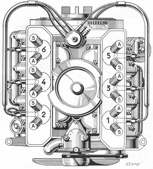
Front of Engine
(A = Inlet - S = Exhaust)
Cylinder order number & valve position
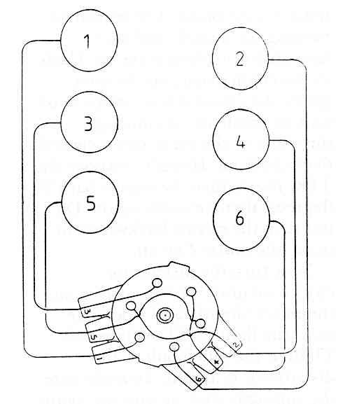
Cross Connections inside distributor cap, viewed from above.
The bold numbers mean 1st in firing order etc. & are marked on cap.
The numbers in brackets are the cylinder numbers
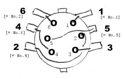
Firing Order
Pistons fire by the cylinder number thus: 1 - 4 - 3 - 6 - 5 - 2, as shown in the above diagram
Markings on Distributor Cap & Cylinder Heads
The distributor cap & cylinder heads (stamped near the spark plug hole) are marked with the numbers 1 to 6.
The numbers mean the 1st in the firing order, the 2nd in the firing order etc. In other words, cylinder 1, then 4, 3, 6, 5 & 2.
In an original set-up one would only have to connect 1 on the distributor cap to 1 on the cylinder head, 2 to 2, 3 to 3 etc.
The left cylinder head is straightforward as the firing order shows. The right side is confusing at first. As the cylinder heads are interchangeable, a non-original set-up could be even more confusing.
The other source of confusion is the order of the numbers on the distributor cap.
This is surely to simplify the route of the plug leads in the engine compartment, & is dealt with by the internal wiring of the cap, as shown in the diagram below.
Ignition Timing
Adjusting the fixed advance
The Aurelia distributor is set with a fixed advance setting of 13-14 degrees when, with the 0 mark on the flywheel starting ring tooth lined up with the mark A/A on the flywheel casing, and the valves of No.1 cylinder are closed, the contact breaker points begin to open, and the distributor arm is opposite the contact in the distributor cap connected to the No.1 cylinder.
To proceed as above, the bolt fixing the distributor to the engine block must be at the centre of the slot in the retaining collar.
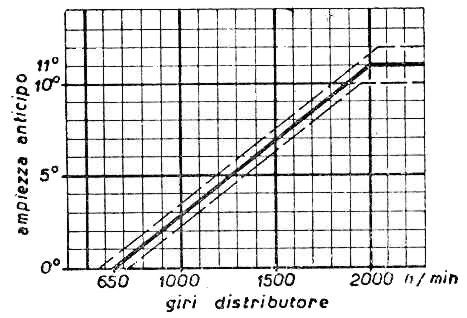
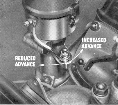
The position may be varied slightly for differing fuels by plus or minus 5 degrees by rotating the collar clockwise or anticlockwise in the slot.
Fitting the Distributor & Setting the Ignition Timing of Aurelia Engines
The following has been edited & retyped from an article by Martin Cliffe (Omicron Engineering Ltd) published in the UK LMC Viva Lancia!Magazine, March 1993 pp. 29 to 31.
- The camshaft timing must be set before the ignition timing can be set. Both contact breakers must be set to 0.45 mm making sure each one is fully open.
- Bring the engine to cylinder No. 1 TDC with both its valves closed. This is when the ‘O’ mark on the flywheel is in line with the ‘1/4’ mark. This means there will be clearance between both valve tips of cylinder. 1 & their rockers. If there is no clearance & the tappets have been set correctly, then the engine is at the end of its exhaust stroke & the crankshaft will have to be turned 360º. Recheck that the rockers rock.
- Install the distributor drive shaft so that the slot lies exactly fore & aft (in line with the longitudinal axis of the engine & car). The slot is offset, so that the distributor shaft will only fit one way round; the offset should be in the direction of the 2-4-6 bank, or in other words, the large segment should lie towards the 1-3-5 bank. There are two complications: the slot at the other end of the shaft has to engage with the oil pump, & the skew gears that drive the distributor make the shaft rotate as it slide down to mesh. Usually trial & error is required to get a correct fit & the engine may need to be turned to engage the oil pump. Slight downwards pressure on the shaft will help you feel when engagement occurs, but the engine must be brought back to the TDC position to see if the slot is still fore & aft. You may have to do this several times, moving it a tooth at a time, but patience will be rewarded.
- Next install the distributor mount aluminium casting with its lug for the clamping screw facing front & right.
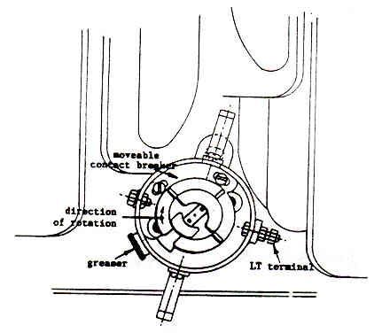
- The distributor itself may now be fitted, ensuring the clamp is in place with its pinch bolt to the rear, close to the greaser cup. The correct position is for one of the two spring clips for holding the cap to be in line with the lug on the distributor mount & the greaser to be towards the rear left of the engine, as shown in Figure 1. Screw the M6 bolt through the clamp into the mount & tighten it so that the screw is roughly in the central part of the slot. The distributor will still turn because the pinch bolt has yet to be tightened.
- The distributor must now be timed so that the spark occurs at the correct point, & the two contact breakers are correctly in phase so that all 6 cylinders fire at equal intervals. Proceed as follows:
- Rig up a test light consisting of a 12 V battery & a low wattage bulb. Connect one side of the battery (say negative) to an earth on the engine, & the other, positive side of the battery to the light bulb. Complete the circuit by connecting the other terminal of the light bulb to the low-tension terminal on the distributor. Obviously the light will come on as long as one or other sets of points is closed. Turn the engine in the opposite direction to normal running (anti-clockwise) by about 30º & then forwards until the TDC mark on the flywheel lines up with the fixed ‘AA’ mark on the engine block. The reason for turning backwards & then forwards is to eliminate the backlash in the chain gear & the skew gears. Any critical movement must only be made in the running, clockwise direction, when viewed from the front of the engine. If you overshoot the TDC mark repeat the above procedure.
- Now turn the distributor until the light comes on, then very slightly anti-clockwise until the light just goes off. Tighten the pinch bolt so the distributor is locked tight. To make sure the ignition timing is correct, turn the engine back by 30º, and then turn forwards slowly. The light should be on & go off exactly as the ‘O’ mark passes the ‘AA’ mark. If not, make a slight adjustment to the distributor position & repeat until correct. The engine is now timed for ignition on cylinders 1, 3 & 5 & you will have noticed that it was the rear contact breaker that was switching light bulb on & off. This contact breaker is fixed to the distributor plate. The other contact breaker for cylinders 2, 4 & 6 can be moved in relation to the first & it is vital to phase it correctly so that all cylinders fir at equal intervals. This phasing is also known as the dwell angle & may be set in three ways:
- It may be set before fitting the distributor to the engine by fixing a 360º protractor to the spindle & using the same test lamp method it will be possible to see if the light goes off every 60º of turning. The moveable contact breaker must be adjusted until this is achieved & I try to get the error to less than 1º of distributor rotation.
- If you do not have an electronic engine analyser, the best method is to time as described in section 7 above & then turn the engine a further 330º (a full turn less 30º - obviously a further full turn of the crankshaft would bring us back to where we started, noting that all 4-stroke engines fire all the cylinders in two revolutions of the crankshaft, however many cylinders there are). With the test light connected as above, further rotation of the engine should make the light go off as the ‘O’ mark reaches the ‘AA’ mark. This time the front contact breaker will be the switch, the exhaust valve for No.1 cylinder will just be closing & the inlet just opening in the overlap phase, & the rotor will be pointing towards the contact for No.6 cylinder, marked 4 (meaning 4th see Figure 2) on the distributor cap. If the light goes off at this point, the engine is timed & phased correctly. If the light goes off between ‘AA’ & ‘1/4’, then the moveable contact breaker should be moved anti-clockwise, & conversely, if the light goes off before ‘AA’ is reached, the moveable breaker needs turning clockwise.
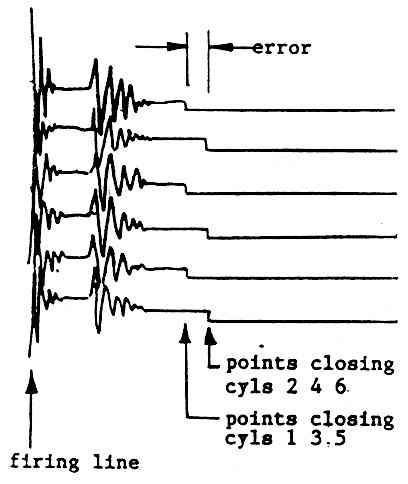
- If you have an electronic engine analyser available with an oscilloscope display you can see the primary or secondary traces above one another. Most analysers automatically align the points opening signal (start of ignition). If all the cylinders are firing equally, the points closing signals should all be directly underneath each other on the display. If they are not, as shown in Figure 3, adjustment of the moveable breaker will bring them into line. There is an advantage in doing this with the engine running as they small variations due to vibration, deflections, running clearances etc. are taken into account & you can also see if one or other cylinder is firing erratically. A worn or bent distributor will also be revealed.
- The initial spark timing should be checked with the engine running by using a stroboscopic timing light. If all was done carefully there should be no more adjustments required!