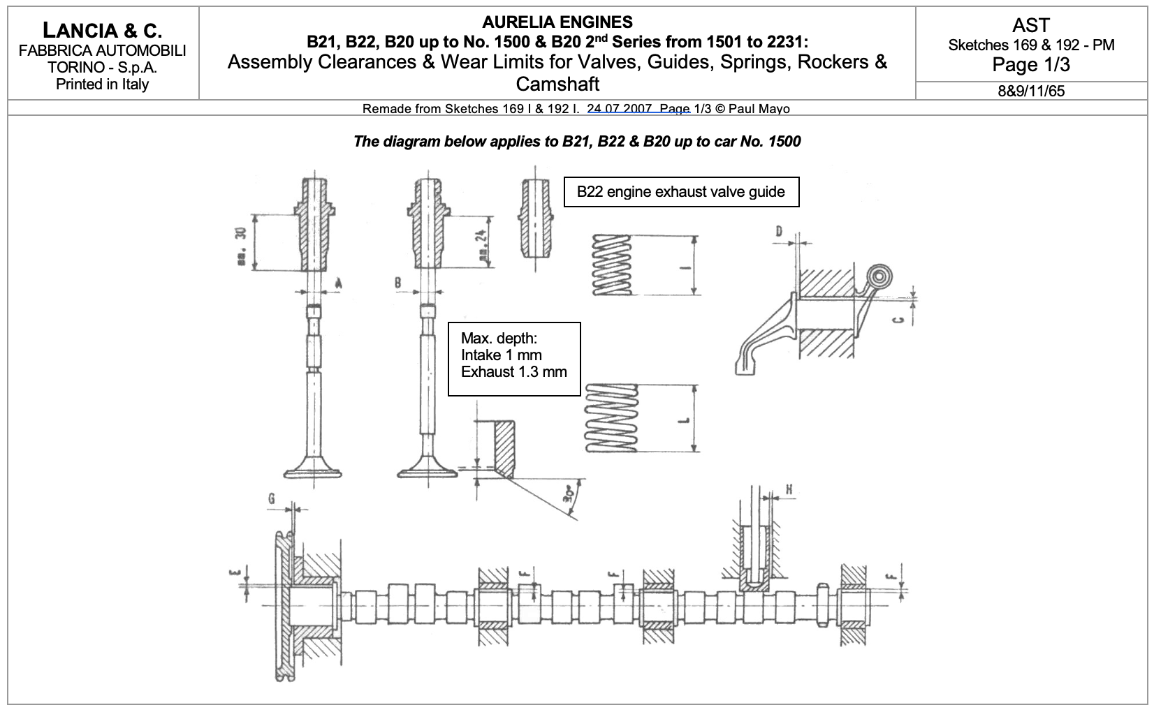
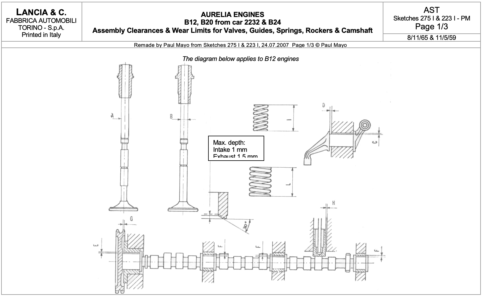
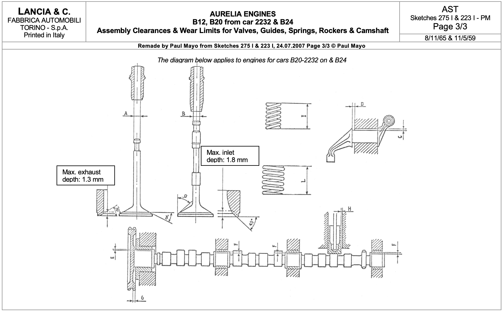
Valve Gear
Tavs. 7 & 8 below show the camshaft, timing chain, rocker gear and valves.
Rocker shaft supports. These should be torqued to 20.25 ft.lbs. or 27.5 N.m, which is the same as the cylinder head studs.
Rocker gear is sometimes the source of noise in the engine, even when tappet clearances seem to be perfect. The rockers should be taken to pieces especially if they do not revolve 360 º freely. Any burrs on the moving faces should be removed with a fine grinding stone. If very bad, the faces may have to be remade & rehardened
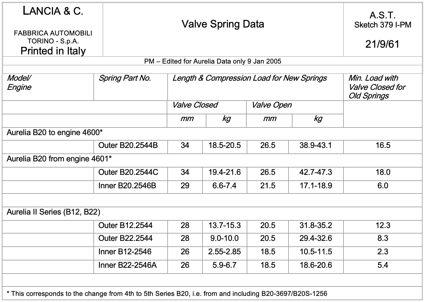
Valve Spring Part Numbers and Applications - 1
| Part Numbers | Application to Model/Engine (vetture/motore) |
|---|---|
| Outer Springs | |
| B10-2544 | B10 |
| B12-2544 | B12, outer exhaust spring |
| B20-2544 | B15, B21, B20 to vett. 1500 |
| B20-2544A | B20 vett. 1500 to 2231 |
| B20-2544B | B20 from vett. 2232 up to mot. 4600 B24 to mot. 1300 |
| B20-2544C | B20 from mot. 4601, B24 from mot. 1301 |
| B22-2544 | B12 outer inlet spring, B22 |
| Inner Springs | |
| B10-2546 | B10 |
| B20-2546 | B21, B15, B22, B12 exhaust valves B20 to vett. 1500 |
| B20-2546A | B12 inlet valves, B20 vett. 1501 to 2231 |
| B20-2546B | B20 from vett. 2232, B24 |
Valve Spring Part Numbers and Applications - 2
| Part Numbers | Application to Model/Engine (vett./mot.) | |
|---|---|---|
| Old No. | New No. | |
| Inlet Valves | ||
| B10-2530 | B10 | |
| B20-2530 | 2129443 | B21, B15, B22, B12, B20 to vett. 1500 |
| B20-2530A | B20 from vett. 1501 to 2231 | |
| B20-2530B | B20 from vett. 2232 | |
| B20-2530D | 2129604 | B20 to mot. 3832, B24 |
| Exhaust Valves | ||
| B10-2532 | B10 | |
| B12-2532 | 2131633 | B12 |
| B20-2532 | B21, B15, B20 to vett. 1500 | |
| B20-2532A | B20 from vett. 1501 to 2231 | |
| B20-2532B | B20 from vett. 2232 up to mot. 2973 | |
| B20-2532C | B20 from mot. 2974 to 3832 | |
| B20-2532D | 2129607 | B20 from mot 3833 |
| B22-2532 | B22 | |
| B20 valves from mot. 4601 and B24 from mot. 1301 are different from those preceding – see Sketch 223. Part no. not obvious from parts catalogue |
Rocker Gear
Tav. 8 from Series I Spare Parts Catalogue

Tav. 8 from Series II Spare Parts Catalogue, Stampato n. 8798512 (August 1959)


Camshaft

Tav. 7 Camshaft & Timing Wheel
| Ref. in Tav. 7 | Description | No. Used |
|---|---|---|
| 1 | Camshaft – see next page for more information | 1 |
| 2 | Sprung ring locating front centre camshaft bearing | 2 |
| 3 | Sprung ring locating rear centre camshaft bearing | 2 |
| 4 | Sprung ring locating rear camshaft bearing | 1 |
| 5 | Spring washer for camshaft wheel locating bolt | 1 |
| 6 | Tensioner arm | 1 |
| 7 | Timing chain | 1 |
| 8 | Split pin | 1 |
| 9 | Front centre camshaft bearing | 1 |
| 10 | Rear centre camshaft bearing | 1 |
| 11 | Rear camshaft bearing | 1 |
| 12 | Front bearing and support | 1 |
| 13 | Locating pin for Vernier adjustment of timing wheel | 1 |
| 14 | Spring for tensioner arm | 1 |
| 15 | Pivot pin for tensioner wheel | 1 |
| 16 | Tensioner wheel | 1 |
| 17 | Locating washer for timing wheel fixing bolt | 1 |
| 18 | Spacer washer for tensioner wheel pivot pin | 2 |
| 19 | Spring washer for timing wheel fixing bolt | 1 |
| 20 | Needle rollers for tensioner wheel – RIV 91123255 – 2.5 mm diameter, 15.8 mm long | 18 |
| 21 | Timing wheel | 1 |
| 22 | Timing wheel fixing bolt | 1 |
| 23 | Bolt fixing front bearing/housing to cylinder block | 2 |
To remove the camshaft, remove the flywheel and behind it the end-cap of the camshaft. Remove the push rods etc. Undo the 3 bolts in the centre of the ‘V’, which locate the camshaft bearings with pegs. Then pull out the camshaft from the rear of the engine, having detached the sprocket wheel and chain at the front.
Standard Camshafts Fitted to Aurelias
Analysis of the Spares Parts Catalogues and the camshaft timing data indicate there to have been four standard timing diagrams and five camshafts. The ‘extra’ one is the B22, the details of which are not yet clear.
Detailed camshaft profile data has become available.
| Camshaft Type | Car Model | Camshaft ‘con tappo’ | Camshaft | ||
|---|---|---|---|---|---|
| Old Part No. | New Part No | Old Part No. | New Part No. | ||
| A | B10, B15, B12, B21, B50-B53 B20 to mot. 2500 - vett. 2231, i.e. 1st & 2nd series | B10-039/1R | 1190503 | B10-2515 | 2125901 (B12 parts list) |
| B | B22/B22S | B22-039/1R | B22-2515 | ||
| C | B20/B20S mot. 2500 to 4600 – vett. 2232 to 3696, i.e. 3rd & 4th series, B24 to mot. 1300 Tipo Europa | B20-039/1R | 1190504 | B20-2515 | 2129600 |
| D | B20/B20S from mot. 4601 – vett. 3697 B24S from mot. 1301 | B20-039A/1R | 1190505 | 2129601 | |
| E | B24 to mot. 1300 Tipo America | B24-039/1R | 1190507 | 2134705 | |
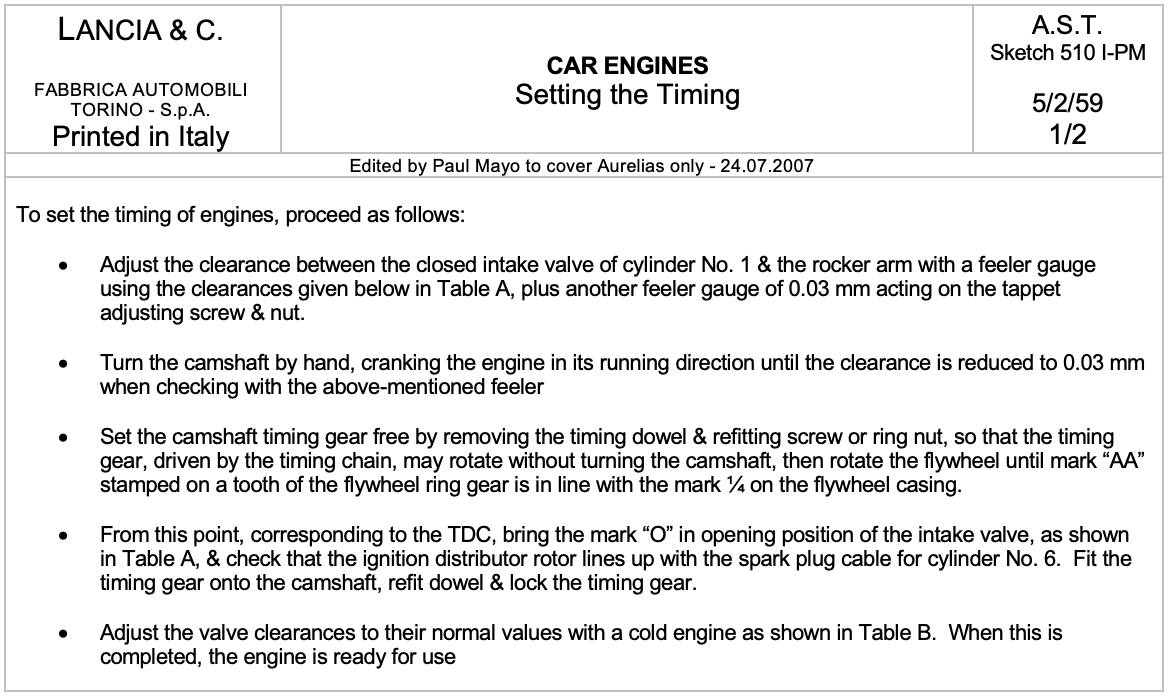
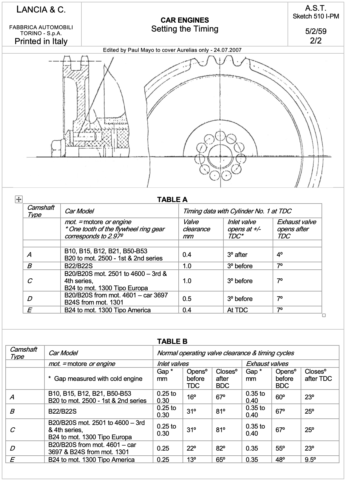
| See Sketch 510 below for the timing data on these camshafts |
Setting the Camshaft Timing of Aurelia Engines
The following is from an article by Martin Cliffe (Omicron Engineering Ltd) published in the UK LMC Viva Lancia!magazine March 1993 pp. 28-29
Lancia’s Method
There are more ways than one to time an engine’s camshaft. Lancia’s method, which was specified in all their service data, was to set the valve clearance of cylinder number 1 to a special timing value & then turn the engine until this clearance was reduced to zero (see Sketch 510 above). The crankshaft would then be at a specified position, varying from model to model, but typically in the range 3º before TDC to 3º after TDC. The reason for using a special valve clearance for timing purposes was to avoid the inaccuracy that would be caused by attempting to time the engine with the cam follower on the quietening ramp of the lobe, where there is a lot of rotation for very little lift.
The procedure works well with an unworn camshaft, but can result in some inaccuracy with a used camshaft. Also, when both inlet & exhaust valves are operated by the same cam, you can accurately set the inlet timing, but find an error on the exhaust.
The Maximum Opening Point (MOP) Method
The following method works equally well with new & moderately worn cams, but bear in mind that it is impossible to accurately set a badly worn cam.
Instead of timing at the opening or closing of the valve, we refer to the maximum opening point (usually abbreviated to MOP), which can be found from the published timing data, & a typical value for the inlet MOP would be 110º of crankshaft rotation after TDC.
Because the cam follower is only moving very slowly around its fully open point, an accurate method of finding the true MOP must be adopted, rather than attempting it by eye. The following procedure is based on an Aurelia B20 4th series, but should be useful for any engine using the applicable data.
Cam timing data is inlet valve opens 31º BTDC; inlet valve closes 81º ABDC; exhaust valve opens 67º BBDC; exhaust valve closes 25º ATDC.
Find the inlet duration by adding 31+81+180 = 292 crankshaft degrees. For a symmetrical cam (all Lancias), halve this value to obtain 146 & then subtract the opening point of 31º to obtain the MOP of 115º ATDC.
Another advantage of this method is that you have no need to know the exact tappet clearance at which the timing figures were quoted. As you will appreciate, a small change in the clearance always results in a large variation in the apparent timing. Lancia, in common with most manufacturers, did not always make it clear at what value their timings were measured.
Finding True Top Dead Centre (TDC) & Marking the MOP on the Flywheel
Assuming the cylinder head has not yet been fitted, verify that the TDC marks on the flywheel are accurate & correct them if an error is found. I have always found Lancias to be very precise, but sometimes flywheels are turned to even out tooth wear (individual balancing means this is an acceptable practice).
The best way to find true TDC is with a dial indicator gauge bearing on the piston crown. Zero the gauge at the estimated TDC position, turn the engine backwards until the piston has descended by roughly 0.050 inches & the rotate it forwards until the dial gauge reads 0.010 inches before the estimated TDC. Make a temporary mark on the flywheel opposite the fixed timing mark stamped ¼ on the block, & then continue turning the engine forwards. The dial gauge will approach its zero (but don’t worry if it dwells close to, but not actually on zero) & then move the other way as the piston starts to descend. Continue turning the crank forwards until the dial gauge reads 0.010 inches again & make a secondary mark on the flywheel.
Now, using dividers or a tape measure, bisect these two temporary marks to find the true TDC. If this coincides with the existing TDC mark, well & good. Lancia used an ‘O’ mark stamped on the ring gear teeth.
Next, mark the flywheel with the desired MOP, measuring from the true TDC & being careful over the direction of rotation to ensure you are marking degrees after TDC & not before. You can do this by some simple geometry, or by using a protractor, but finding the true centre of the flywheel adds more work. Figure 1 should help make this clear. See Sump, Crankcase & Crankshaft, Cylinder Block & Pistons for more information on the flywheel.
Timing the Engine Approximately
For the next stage the camshaft must be installed with its sprocket loosely attached, but without the timing chain. Fit the No. 1 inlet cam follower (to save looking at the head this goes in the second bore from the front) making sure that unless new followers are being used you fit the old followers in their original positions – you did number them? Now arrange the dial gauge to bear on No. 1 inlet follower by using the valve push rod. Adjust the position of the dial gauge so that the full range of the follower movement is recorded, & turn the cam by means of its sprocket until the maximum lift is indicated. Zero the dial gauge & without allowing either the cam or crank to move, fit the timing chain & insert the dowel in whichever pair of holes line up. The cam is now approximately timed.
To set the timing accurately, use a similar procedure to finding the true TDC in the following way. Turn the engine backwards (anti-clockwise) until the dial gauge reads about 0.050 inches before maximum lift. From now on only turn the engine forwards, which avoids the backlash in the chain causing an error, & stop when the dial gauge reads 0.020 inches. If you overshoot, return back past this point & turn forwards again to the 0.020 inch point. Make a temporary mark on the flywheel. Continue turning the engine through the zero point & until the gauge reads 0.020 inches again (i.e. with the cam follower falling) & mark the flywheel a second time.
Timing the Engine Accurately
Fixed Timing Marks:
1 4 – Cylinders 1 & 6 at TDC
AA – Initial ignition advance
0 – Rotating TDC mark on flywheel

Figure 1: View of the flywheel from the rear of the engine showing timing marks
& cylinder No. 1 inlet valve maximum opening point (MOP)
Obviously, the true MOP is halfway between these last two marks. If you are very lucky you may find the bisection coincides with the MOP you have marked on the flywheel, but more likely is that you will find a small error. To correct this move the dowel pin one hole & repeat the exercise until you get as close as possible to the true MOP. A small amount of trial & error is required. I know it sounds complicated but in practice it only takes a few minutes. Sometimes you cannot achieve exactly the desired timing because even with the Vernier dowel system you can only move the timing in discrete steps (12 holes in the cam & 11 in the sprocket results in increments of 2.72 cam shaft degrees or 5.45 crankshaft degrees).
Once you are satisfied that you have the correct setting, the timing sprocket may be fully tightened & there should be no need to repeat the exercise on the exhaust lobe. Of course this do not apply to twin cam engines, for which each cam has to be individually timed using the same method.
Setting the Valve Clearances of Aurelia & Flaminia Engines
Setting tappets on overhead cam engines is easy as you can readily observe when the follower or rocker is on the back of the cam, although I agree that removing cams or extracting reluctant shims can present a challenge. When the cam is out of sight a different method of checking whether the cam is in the correct position is required & I have found the following sequence to be useful for Aurelias & Flaminias:
| Inlet valve fully open | Set inlet valve | Set exhaust valve |
|---|---|---|
| 1 | 6 | 2 |
| 4 | 5 | 1 |
| 3 | 2 | 4 |
| 6 | 1 | 3 |
| 5 | 4 | 6 |
| 2 | 3 | 5 |
The above order of cylinders is based on the standard cylinder numbering which is:
Front of Car & Engine