Cooling System
Tav.22 for B12 etc. from Series II Parts Catalogue. Very similar to Series I System

Thermostats
The cooling system is very similar for all models. Two thermostats are used, one in the top outlet pipe (part 64 is Tav. 22 above) which divides into two flanges entering the header tank on B20 and B24 models, and one in the header tank (part 63) operating the shutters (part 31). Both thermostats operate between 65 and 75 º. Celsius.
The shutter thermostat can become sluggish with its operating temperature getting higher until it fails to work. To replace, unscrew the threaded retaining ring (part 38) with a 4-pronged key. This may be very difficult, and the holes may have to be enlarged in order to use a drift to try turning the retainer. If this fails, more brutal methods may be needed.
Part 38 seem to have been of steel and then later of aluminium. On assembly, silicon or copper grease will assist. Use two, fibre, washers (13). These were originally made of lead.
The Appia thermostat will fit, but is smaller in diameter, resulting in an increased flow of water which may be useful.
The main thermostat can also be very difficult to remove as the alloy supply pipe (34) to the header tank is threaded on to the thermostat housing (54) with a fine thread and is invariably corroded together. Heating may help, but parting these two items is hazardous and usually results in damage. It is as well to have spare parts available. These have been remanufactured from time to time.
Part (34) has been reproduced long ago in bronze, which makes it far more durable.
The thermostat generally ‘fails safe’ in the open position, and thus the engine is overcooled and the heater inefficient. This can be a major nuisance in a cold country!
Coolant and System Maintenance
It is advisable to flush the system twice a year, especially the heater. Occasionally remove the radiator core and reverse flush to remove lime scale, which can form in the header tank and elsewhere. In fact in hard water areas it is best to use de-ionised, distilled, or soft water or inhibitors as the long term results of hard water and lime deposits are serious corrosion and inefficiency inside the engine.
Drain off 1 pint of coolant every 2 months via the drain tap (50) to allow sediment to be removed. Silting up of the block is common especially in hard-water areas. The reinforced flexible hose (66), which passes from the block near the rear of the fuel pump to the drain tap (50), can become blocked with sludge and stop water flow. It only drains the right side of the block and only to the level of the water pump. The left side of the block is supposed to drain via a small, and frequently blocked, drilling across the rear of the block near the rev. counter drive boss. This lack of draining of the block can leave it vulnerable to frost damage, which may not reveal itself externally. Interior cracking may occur which weakens the block wall and allows it to move under the upward pull of the head studs leading to subsequent blown cylinder head gaskets. Moral - full draining requires inversion of the engine, and always uses some anti-freeze.
The external alloy water pipes can become very eroded on their inner surfaces and the steel pipes within the engine block can disappear completely.
Temporary repairs of the alloy pipes can be made with thorough wire brushing and finishing with epoxy resin or fibreglass.
Water Hosing (Refer to Tav. 22 above)
Both main water hoses maybe replaced with 1 inch/25 mm bore rubber hose. The radiator top hose may be replaced by an Austin A40 hose. Although the original is bulbous, engine movement is so slight that a parallel hose serves well.
Radiator bottom hose (20) goes from the drain tap to the water pump. Length 160 mm (4th series B20), and for an outer diameter of 35 mm use Jubilee clips size 1.
To replace, with engine in situ, loosen both jubilee clips, remove the two 10 mm nuts holding water pump intake pipe to housing and pull off studs. Note thin gasket, which should be replace or reassembled using gasket compound. Fitting new hose is aided by using Vaseline.
Fan Guard Tav. 21 #26 SI & Tav. 22 #26 SII – See Diagram Above
There are 4 types of fan-guard. The B20 type is for all series & originated with the B50-series of cars.
| Part No. | Model Application | Notes |
|---|---|---|
| B10-75696 | B10, B15, B21, B22 | |
| 82128134 | B12 | |
| 82144164; B50-75696 | B20 All Series, B50-series | |
| 82134867 | B24 |
Coolant Required for Aurelia Models
Internal corrosion can be inhibited with the following mixture: a solution of 5% sodium benzoate and 0.5% sodium nitrate in distilled water added to the coolant in the same proportions as you would with anti-freeze. Commercial inhibitors are of course available. Normal anti-freeze can be used as follows:
| Car type | Volume of Cooling System Pints (Litres) | Antifreeze (Bluecol AA was the example used) Pints (Litres) | ||
|---|---|---|---|---|
| 25% | 33.30% | 50% | ||
| All types | 18.5 (10.5) | 4.5 (2.6) | 6 (3.4) | 9 (5.1) |
| Safe driving to º. Celsius | Minus 12 | Minus 20 | Minus 36 | |
| Safe from frost to º. Celsius | Minus 26 | Minus 35 | Minus 48 |
In some instances it has been found that normal glycol antifreeze has caused internal corrosion of the aluminium alloy.
A recommendation to counter this possibility is the use of central heating system protectors such as Fernox Alphi-11 Protector (http://www.fernox.com/). A full data sheet is available from this website.
Fan, Fan Belt and Water Pump

Tav.23 Water Pump, Series II Diagram (B12 etc.)
Although very similar for all models there were several subtle modifications to the water pump.
Notes on Tav. 23 - Water Pump, Fan and Fan-belt


The following article is by Carter Hendricks, originally published in Lanciana (ALC), May 1994 & reprinted in Viva Lancia! (UK), January 2005.
I have added comments, where appropriate, and the part numbers (e.g. 23#6) from Tavs. .22 & 23 above, which depict the B12 and not the B20 where some parts look different.
The Aurelia water pump is a little piece of art. And while I still think that the intent of the separation of impeller shaft from fan loads was to decouple the loads, I don’t think now that it would have worked that way very well. Still: it is the intentions which others can judge and which we can marvel at.
The Aurelia, according to automotive journalist and historian L.J.K. Setright, “was a car typical of Lancia, in that it was much too good for its own good”. He was speaking particularly of its V6 engine. A recent simple mechanical operation on my 4th Series coupe shows just how right Setright speaks. If the Aurelia is too good for its own good, its water pump is far too good for a water pump.
I removed the water pump from my car not to marvel at its engineering, but to replace bearings which had at last gone loose and noisy. I drained and discarded the coolant, removed the Y-shaped upper water distribution manifold (22#34), and recognised the importance of annual coolant renewal for an aluminium engine. I cleaned a small amount of corrosion from the inside of that pipe and protected its surface with silicone grease.
The actual removal of the water pump is a straightforward procedure. Disassembly of the pump is made simple by Dr. Ing. De Virgilio’s thoughtful design. Pullers or presses are not required to strip down the pump. Instead, threaded bosses are tapped into the main components. I progressively tightened a pair of bolts in these holes and the fan hub and pump cover fell off in my hands (this is true elsewhere on the car – PM).
The fan has a floating hub (23#5), independent of the actual water pump. Two ball bearings (23#8) are spaced directly under the pulley centre line and absorb drive loads. This careful placement of bearings also reduces side loads. All of these loads are isolated from the pump’s drive spindle (23#1).
The pump spindle picks up its rotation from the front of the fan hub (23#17) in a coupling, which permits slight misalignments. The spindle is supported by a bronze bushing (23#5) centred on the slender shaft. Sealing functions are performed by a carbon ring 23#2). Drilled passages and channels in the hub and bronze bushing allow ample lubrication (from the greasing point 23#16 – PM).
The Aurelia water pump is beautiful and excessive in its design. Drive and fan loads are isolated and dealt with by a pair of large ball bearings, just like the car’s wheel hubs. The ‘drive shaft’ water pump spindle floats independently in a wide bushing. The only fault is expense. Countless complex machine operations are held to tight tolerance. Hubs, bearings, bushings, spaces are expenses offered to an ideal of excellence not often shared with the ultimate driver. The Ferrari water pump used on the V12 is agricultural in comparison – but more than adequate. The advantages of the Aurelia water pump are academic and unseen in use.
The excellent handling, fair performance and wonderful lines of the Aurelia sold a good number of rather expensive automobiles. The excesses throughout the car made each sale a dubious success. The losses mounted. A car “too good for its own good”, according to Setright. “The finest thing you’ll ever own”, according to Tom Sheehan. They’re both right.
The Aurelia Water Pump
Article by Peter Renou, published here September 2025
In the Aurelia Water Pump the seal is a hardened steel disc working against a white metal face. It is a beautiful design, rarely gives trouble and is easy to service.
In the photographs the hardened steel disc A is sealed to the impeller and shaft by O-ring B.

This disc works against the white metal face C and pressure on the seal and O-ring is maintained by the spring at the front of the fan hub.
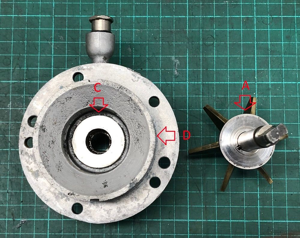
I have not had to re-surface the hardened disc but a couple of times I have had to take a light cut off the white metal face. Most often, all that is needed is to replace the O-ring sealing the hardened disc to the impeller and shaft. The ball bearings are obtainable in sealed form so the seals should be removed on one side to allow grease to reach them and the brass bush which supports the shaft.
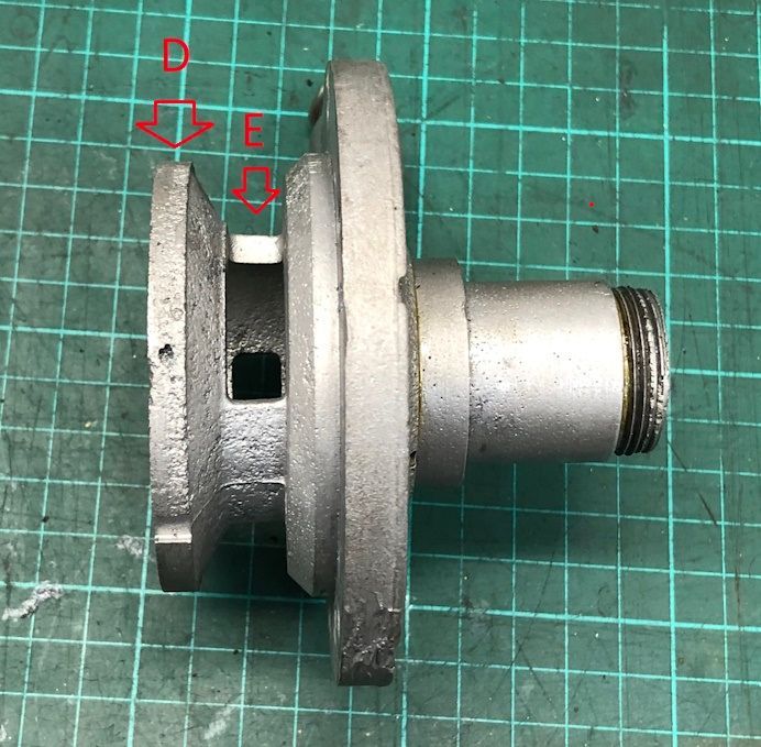
In dismantling the pump a special spanner is needed to undo the castellated nut (11) so the fan and bearings can be removed. When removing the front cover there is a trap for young players. Sometimes with internal corrosion the disc D is firmly stuck in the body of the pump and, if excessive force is applied by the bolts pushing the front cover off the body, it is possible to break the three pillars E attaching the disc D to the front part of the cover. Heat to the pump body for disassembly can avoid this unfortunate outcome.
In the parts drawing 18 is the tensioning spring, 8 are the ball bearings, 28 is the white metal face, 27 is the hardened steel disc and 2 is the sealing O-ring.
Peter Renou.
Radiator Dismantling & Overhaul – 3rd/4th Series B20s – Refer to Series II Tav. 22
A: Two 14 mm head, 97 mm long 8 x 1.25 thread, long shoulder bolts securing front guard & on other side the entry casting with drain tap etc.
B: 18 mm long, 6 x 1.00 threaded stud with 10 mm sided nut securing front guard.
C: Shutter control mechanism
D: Upper stays – see below for details.
E: One of the four shutters. The upper one is detachable but the others are linked together.
F: Protective guard
G: Position of shutter thermostat located in radiator header tank.
H: Position on a 4th Series of temperature gauge sender unit.
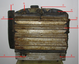
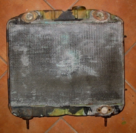
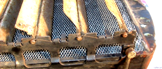
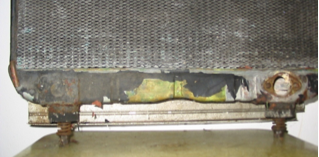
View of a 3rd series B20 radiator from front of car
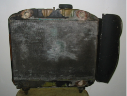
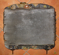
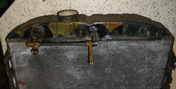
View of above radiator from engine side.
Note shutter thermostat on right side of header tank protruding into outlet casting.
The two flanges at either side of the upper tank are to locate the outlet casting. The fixings are four bolts (10 mm heads) 5 x 1.? mm threads, 20 mm long with plain & spring washers & gasket as below:

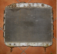
View of front face of stripped radiator. Extra hole in top tank visible below filler, & pressed depression that could take temperature gauge sender on right.
View of rear face of stripped radiator.
View of third series B20 radiator from front right side of car showing guard, complete shutters & actuating mechanism & radiator cap. Hanging down in a vertical position is the right hand upper stay.

Similar view of third series B20 radiator from front left side of car. Fixing stay hanging down.
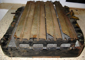
Fourth Series radiator, top view, front face uppermost. The extra hole on right of filler is non-standard & was repaired. Splits round filler casting & other splits covered with solder all over top tank. Fittings to header tank, & shutters dismantled. Note 3 rows of tubes in core of radiator.
4th series radiator, Front face. Loose bottom mounting on left. Mounting for temperature gauge sender at top right
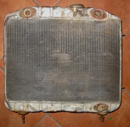
4th series radiator – view of rear face
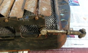
Radiator Shutter Actuation
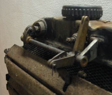
This Series 3 radiator has had a temperature gauge sender added below the radiator cap.
Clevis pin, washer & split pin connect actuating arm to adjustable shutter lever.
The actuating bar is 8 mm dia. steel & is a very close fit to the bronze levers mounted on it with tapered pins.
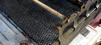
3rd Series shutter actuation with shutters removed. Non-standard temperature gauge sender visible below filler on right.

4th Series top tank, front face, showing temperature gauge sender mounting at right side.
Shutter thermostat & Temperature Gauge Sender
Shutter thermostat, later type with parts for fitting into top tank. From right, steel, threaded retainer with 4 pinholes to tighten, lead sealing ring, steel locating half-rings, 2 lead sealing rings. This one came from a 4th Series B20.
Cold, no extension of piston.
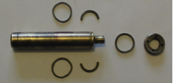
As above, but with plunger extended.
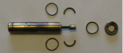
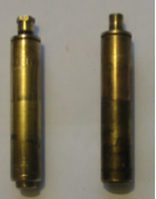
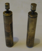
Two types of shutter thermostat, closed & extended.
The earlier type seems to be the one with the hex-headed piston, which is adjustable on a threaded rod. The other type is not adjustable, but the shutter-opening cam is adjustable
Temperature gauge sender used on 4th Series with Jaeger instruments

Radiator Shutters
This view shows the steel wire, which holds the shutters in place following a simple route over & under the folds in the side chassis.
A close up view of the upper end with upper stays (#65/72) consisting of short, adjustable rod (14 mm sided adjusting nut).
At the radiator are a special 14 mm head bolt (#2 2128133), nut & plain & spring washers, 22 mm long 8 x 1.25 thread with about 14 mm shoulder.
At body side is a 10 mm head bolt, nut & spring washer, 25 mm long 6 x 1.0 mm thread with 8 mm shoulder.
The small Silentbloc (#71, 2049636) is 14 mm wide x 17 od x 6 id & was originally RIV 88206322.
A close up view of the lower end showing the wire wrapped round the bottom peg.
A close up view of the upper end with upper stays (#65/72) consisting of short, adjustable rod (14 mm sided adjusting nut).
At the radiator are a special 14 mm head bolt (#2 2128133), nut & plain & spring washers, 22 mm long 8 x 1.25 thread with about 14 mm shoulder.
At body side is a 10 mm head bolt, nut & spring washer, 25 mm long 6 x 1.0 mm thread with 8 mm shoulder.
The small Silentbloc (#71, 2049636) is 14 mm wide x 17 od x 6 id & was originally RIV 88206322.
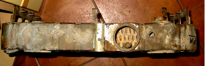
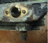
Bottom of Radiator
Lower part of radiator from engine side showing two lower mountings, bottom tank & flange for inlet casting at right (with ends of Bolts A in first photo above). There is a gasket as follows:

Left & right lower mountings to cross member of body above front axle.
A stud (50 mm long with 29 mm of 10 mm wide shoulder & 21 mm thread 8 x 1.0 mm) is secured into a cup in the bottom tank with lead, then there is a rubber buffer (shaped to fit bottom tank, otherwise 19 mm deep, 47 od 10-12 id), a spring (31 mm long, 20 mm wide with 5 coils of 2.5 mm wire, a retaining cup washer (24 mm od, 8 mm id) & two, locking nuts, 14 mm across faces
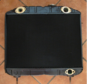
Overhauled Radiator
The radiators were taken to Gloucester Radiators (01452 419524) for overhaul.
Repairs were made to the tanks and a new modern core fitted.
The fitting for the 4th series temperature sender was easily removed & fitted to the earlier radiator top tank, which in this case was in better condition.
The new core (Reference No. SP33057) is 335 mm high by 475 mm wide, 3-row S-type with 12 fins per inch & central folded square corners. Top & bottom tube plates are 478 mm by 65 mm.
Each face is covered with a convincing meshed masking panel to replicate the original appearance.
The old radiator weighed at least 13.3 kg whereas the overhauled one was 8.4 kg – 63% of its former weight. Cost of repair £350.
Opposite: The front face of the overhauled radiator showing, at the top right, the temperature sender fitting transferred from another radiator.

Opposite: The rear, engine-side face of the overhauled radiator showing clean flange surfaces & threads.
The mesh covers the new core to give an ‘original’ appearance
Opposite: The top of the overhauled radiator showing the new core through the radiator filler.
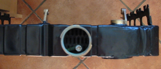
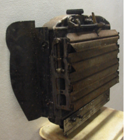
A side view of the overhauled radiator before any components have been refitted.
The 8 mm bar which fits into the two mountings on the header tank, (see left side of photo) was also given to the radiator overhaul specialist to make sure they were exactly in line after any disturbance during overhaul. The rod is a very close fit.

Radiator Mounting Rubbers
