This is paragraph text. Click it or hit the Manage Text button to change the font, color, size, format, and more. To set up site-wide paragraph and title styles, go to Site Theme.
Carburation & Fuel System
General Arrangements for Different Models
The following schemes show some of the general arrangements of the fuel systems used on Aurelia models. There were many variations in fuel tank design, fuel gauges, position of the fuel reserve tap, fuel pump type, carburettors, air cleaner type & number & design of the exhaust system. There were of course modifications made to cars in the after-market with Nardi conversions being amongst the most well-known (Performance Modifications).
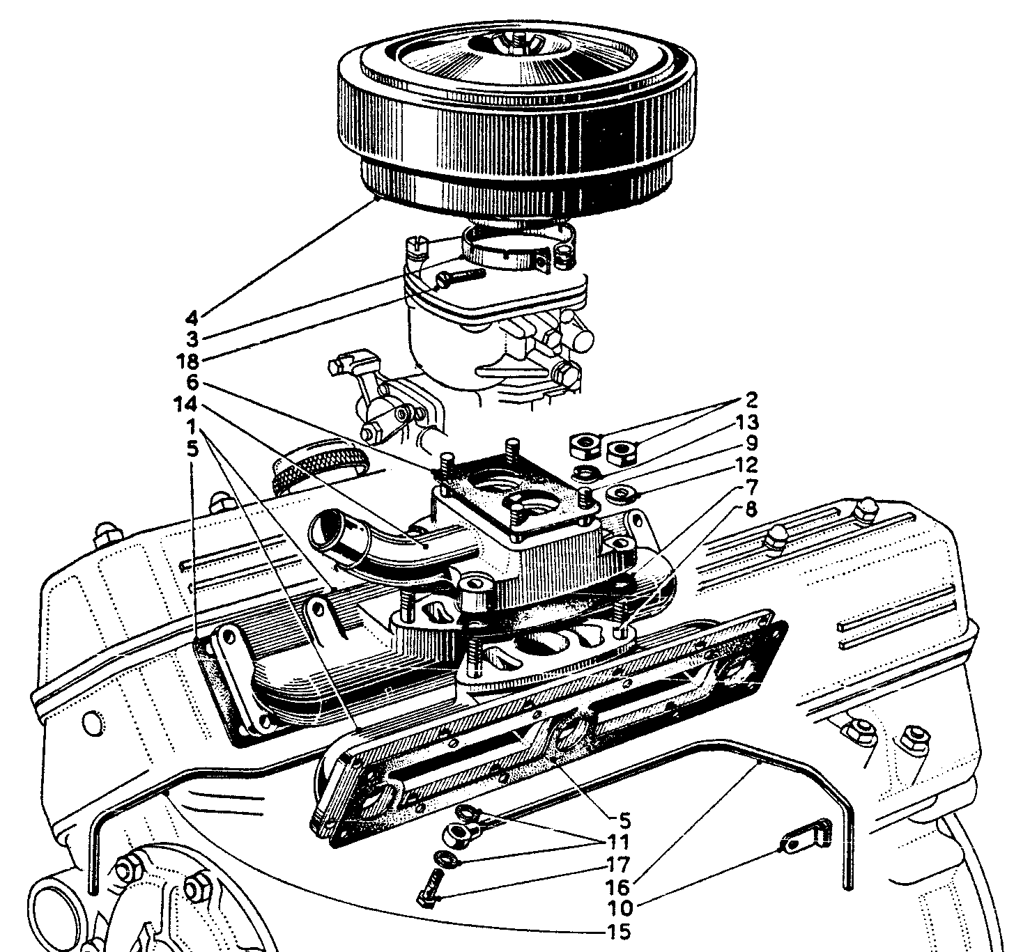
Tav. 10 for Cars up to B10-2935, B50-1427, B51-1073 & B21-1038

Parts List for Tav.10 above & Tav. 10bis below
| Ref. Tav. 10 | Ref. Tav. 10bis | Description | Lancia Part No. | No. Used |
|---|---|---|---|---|
| 1 | 1 | Carburettor Solex 30 AAI – C-19810 | B10-5011 (S) | 1 |
| 2 | 2 | Inlet manifold | B10-045R | 2 |
| 3 | 3 | Exhaust manifold | B10-1400 | 2 |
| 4 | 4 | Air filter | B10-0768R | 1 |
| 5 | 5 | Petrol line union | Git 8 | 1 |
| 6 | 6 | Fuel pump – Tipo Alit On the later cars Tav. 10bis Tipo Alit Excelsior & Tipo Fispa were available | B10-5101 & then – (A) & - (F) | 1 |
| 7 | 8 | Fuel tank – on the later cars there is a reserve outlet on the tank, tap #7 (B10-81010) & extra fuel pipe #12 (B10-0717R) | #7 = B10-0718R #8 = B10-0718BR | 1 |
| 8 & 9 | 9 & 10 | Exhaust silencers – these are handed R & L & for the earlier cars there were two types, changing from car B10-2000. The later cars had this later silencer. | Earlier type: B10-0741R/0743R Later type: B10-0741AR/0743AR | 1 of each |
| 10 & 11 | 13 & 14 | Fuel drain tubes R & L – same for all cars | B10-0729R/0731R | 1 of each |
| 12, 16 & 15 | 11, 15, 19 & 18 | Fuel pipe from tank, one for early cars, two parts for later cars, plus flexible pipe to fuel pump & flexible pipe to carburettor | 2 or 3 pieces | |
| 13 &14 | 16 & 17 | Exhaust pipes – these are handed R & L & for the earlier cars there were two types, changing from car B10-2000. The later cars had this later silencer | Earlier type: B10-0745R/0747R Later type: B10-0745AR/0747AR | 1 of each |
| Fuel filter FISPA 2035/FC was introduced on later cars from B10-5143, B10S-1266, B52-1087, B53-1087, B21-3158, B21S-1265 & B20-1751 & on some preceding cars. | B10-5241 | 1 |
Tav. 10 for Cars up to B10-2935, B50-1427, B51-1073 & B21-1038

Tav. 10 For B12 & other 2nd Series Cars

Fuel System for B20 Series 4 Cars.


Fuel Tanks & Level Sender Units & Dashboard Gauges
For information on the fuel gauges see Dashboard, Control & Instruments
The fuel tanks, fuel lines, reserve taps & fuel gauges differed considerably from model to model. The B20 Series 3 was distinctive with its fuel filler placed centrally at the lip of the boot space, whereas in most other models it was place to the left.
The fuel gauge in the B20 Series 4 with Jaeger instruments was in the speedo fitting & was special in using a potentiometer-type tank sender unit with two electrical wires.
Petrol smells, a common complaint on older cars is usually the result of the perishing of the rubber overflow/sloshing pipe
Tav. 11 Series I – Fuel Tank for B10 etc.


Tav. 11 Series II – Fuel Tank for B12
The following table gives details of the fuel tanks & sender units, from which it can be seen that there were 4 types of tank fitted to Series I cars. 1st Series B20s had the B10 later tank, 2nd Series had another tank & 3rd Series had the distinctive centre-filling tank.
For Series 2 there were 3 types for the B12, including an export version, & 2 types for the B20 Series 4, 5 & 6 including an export version & 6 types for the B24 including 3 export versions – a total of 15 types of tank!
Table of Fuel Tanks & Level Sender Units
| Aurelia Model | Fuel Tank Part No. | Note | Fuel Level Sender Part No. | Note |
|---|---|---|---|---|
| Up to B10-2935, B50-1427, B51-1073 & B21-1038 | B10-0718R | Reserve tap fitted to tank & not next to driver’s seat | B10-91212 | Made by Metron S.p.A, Torino, Model CL 12 (L.B10) |
| From B10-2935, B50-1427, B51-1073 & B21-1038, B20-1001 to 1500 1st series, B52/53, B10S, B21/B21S, B15/B15S, B22/22S | B10-0718BR | On the later cars there is a reserve outlet on the tank to a tap next to the driver’s seat | B10-91212 | ditto |
| B20 from 1501 to 2231 (2nd series) | B20-0718AR | B20-91212 | Borletti | |
| B20 from 2232 to 2951 (3rd series) | B20-0718BR | Filler in the rear centre of the tank | ditto | ditto |
| Up to B12-1930/B12S-1564 | 1705935 | Filler to left, rear of tank | 2133398 ex-B12-91212(B) | Made by Borletti S.p.A, Milano, Model IL-519 |
| From B12-1930/B12S-1565 | 1705936 | ditto | ditto | ditto |
| From B12-1930/B12S-1565 For Export | 1705937 | ditto | ditto | ditto |
| From B20-2952 to B20-3420, B20S-1001 to 1130 | 1702078 | ditto | 2131331 ex-B20-91212A(B) | Borletti Model IL-520 |
| B20-3421 to 3696, B20S-1131 to 1255 | ditto | ditto | 2131332 ex-B20-91212B(J) | Made by Jaeger, Milano, Model 66250 |
| B20-3697 to 3816, B20S-1256 to 1436 | ditto | ditto | 2131333 ex-B20-91212C(J) | Made by Jaeger, Milano, Model 29/68956/173 |
| From B20-3817, B20S-1437 | ditto | ditto | 2131334 ex-B20-91212D(J) | Made by Jaeger, Milano, Model 68374/3917/18/158 |
| From B20 | 1702079 | Tank for Export markets | ||
| B24-1001-1059, B24S-1001 to 1181: 4th series –see Note below | 1702080 | Tank with extension, without level gauge | 2136487 ex-B24-91211(B) | Made by Borletti Model IL-521 |
| B24S-1001 to 1181 4th series | 1702081 | Tank with extension, without level gauge for Export markets | ditto | ditto |
| B24S-1001 to 1181 4th series | 1790762 | Tank without extension or level gauge | ditto | ditto |
| B24S-1182 to 1452 | 1702082 | Tank with extension, without level gauge | 2136695 | Jaeger 68956-3917/19/173 from B24S-1182 to 1331 5th series |
| 2136696 | Jaeger 74545-3917/66/243 from B24-1332 to 1452 | |||
| B24S-1182 to 1452 | 1702083 | Tank with extension, without level gauge for Export markets | ditto | ditto |
| B24S-1182 to 1452 | 1790763 | Tank without extension or level gauge | ditto | ditto |
| B24S-1453 on | 1702084 | Tank with extension, without level gauge | 2136697 | Jaeger From B24S-1453 |
| B24S-1453 on | 1702085 | Tank with extension, without level gauge for Export markets | ditto | ditto |
| B24S-1453 on | 1790764 | Tank without extension or level gauge | ditto | ditto |
Note: Not absolutely sure about this for the RHD B24 cars as parts book unclear.
The fuel level senders also changed but only 2 types were fitted to Series I cars firstly one made by Metron & then for the B20 Series 2 & 3 one made by Borletti. For Series II cars Borletti continued to supply for the B12 & another type for the early B20 Series 4 with Veglia main dashboard instruments. From the late 4th Series B20 (B20-3421 on) the senders & dashboard instrumentation was made by Jaeger & 3 types were fitted; the B24s seem to account for another 4 types with Borletti for the 4th Series B24 RHD cars & Jaeger for the rest – a total of 11 types!
Mechanical Fuel Pumps
Five types of mechanical fuel pumps were fitted (see table below) made by ALIT or FISPA.
Tipo ALIT Fuel Pump (Tav. 12 SI) Fitted to B10s etc.

Tipo FISPA Fuel Pump (Tav. 12bis SI) Fitted to later Series I & up to early SII cars
Fuel Pumps fitted to Aurelia Cars
| Aurelia Model | Type of Fuel Pump | Lancia Part No. | Tav.in Parts Book | |
|---|---|---|---|---|
| 1 | B10/B10S, B50, B51, B52, B53, B21/B21S, B20, B15/B15S, B22/B22S | ALIT | B10-5101 | Tav. 12 SI |
| 2 | B10/B10S, B50, B51, B52, B53, B21/B21S, B20, B15/B15S, B22/B22S | FISPA Tipo Y112 | B10-5101(F) | Tav. 12 SI |
| 3 | B10/B10S, B50, B51, B52, B53, B21/B21S, B15/B15S, B22/B22S, up to B20-2231 | ALIT Tipo Excelsior | B10-5101(A) | Tav. 12 SI |
| 4 | B20 from no. 2232 B12 | ALIT Tipo Excelsior This pump differs only in a few internal parts from the B10-5101 version: e.g. the diaphragm return spring & actuating shaft This could be replaced for B12 & B20 cars by the FISPA pump with adaptor parts | B20-5101(A) later 2129651 | Tav. 12 SI Tav. 13 SII |
| 5 | B12, from B20-2952, B20S-1001, B24-1001, B24S-1001 | FISPA mod.SUP.60-1086/P | 2129652 ex-B20-5101A(F) | Tav. 13 bis SII |
Pumps #3 & #4 Tipo ALIT Excelsior differ in minor respects as far as I can see. In the Tav. 13 SII below parts #1, #16 & #22 are the main ones.

Tipo ALIT Excelsior Fuel Pump (Tav. 12bis SI & Tav. 13 SII) Fitted to B10s etc.
On older cars, or any car with a fuel tank of unknown condition, regular cleaning of all fuel line filters is essential. Fuel pump filters #7 in the ALIT Excelsior pump above & #17 in the FISPA pump below are easily accessible at the top of the pumps & should be cleaned with petrol or paraffin.
Tipo FISPA-mod.SUP.60 Fuel Pump (Tav. 13bis SII)

Replacement Parts (rather dated information):
| Lancia Part No. | Description | Replacement Part No. |
|---|---|---|
| 2158594/2158643 #2 & #3 Tav. 13bis SII | FISPA petrol pump lever & arm | FIAT 9901810 |
| 2158650 #14 Tav. 13bis SII | FISPA pump pivot pin | FIAT 9901513 |
| Aurelia pump | Similar type on - | A Peugeot model |
Fitting an Electrical Pump
Many cars have had electrical pumps placed either instead of or in tandem with the original pump. SU electric pumps have been successfully been fitted to many Aurelias. One is driven to this on a car that is not used every day due to the drainage/evaporation of fuel from the carburettor float chambers & supply lines & the subsequent strain on the battery when trying to start the car. The effort to prime the carburettor can flatten the battery with frustrating results. This is especially the case with cold starting in cold weather.
The pump is best connected in the tank to pump pipe before reaching the mechanical pump. If the electric pump is connected through the ignition fuse it then operates as soon as the ignition is on & primes the carburettor immediately. A good place to fix the pump is behind the grille in the cool air flow under the horns.
Fuel & Air Filters
Fuel Filtration
Filters for the fuel supply are fitted in the base of the fuel tank, in the top of the mechanical fuel pump, on some models as a separated glass-bowled filter (see below) & also in the carburettor inlet unions.
See the relevant exploded diagrams for these parts. These filters should all be regularly cleaned or replace to ensure proper running of the vehicle. Cars with suspect fuel tanks & those not fitted with bowl-type filters will benefit from adding a bowl filter or the modern in-line polythene-cased disposable paper filters.
Tipo FISPA 2035/FC Fuel Filter (Tav. 12 SII)

The above fuel filter was fitted as standard to the B12 & B20 from no. 2952 with ALIT Excelsior fuel pumps. On these B20s intended for export a pressure-regulating valve was fitted. Those later B12s, B20s & all B24s fitted with the FISPA fuel pump thus do not seem to have been fitted with a fuel filter as standard.
Air Filtration
Seven different air filters were fitted as standard & numerous after-market & competition/sporting products were used to improve the ‘breathing’ of the cars. The standard air filter housings & filters are described below.
| Models | Lancia Part No. | Notes | |
|---|---|---|---|
| 1 | B10, B21, B15, B22 | B10-0768R | See Tav. 14 SI |
| 2 | B50-51-52-53 | B50-0768R | |
| 3 | B20-1001 to 1500 | B20-0768R | |
| 4 | B20-1501 to 2231 | B20-0768AR | |
| 5 | B20-2232 to 4011 | B20-0768BR later 1702392 | |
| 6 | B12 | 1702398 ex-B12-0768R | See Tav. 15 SII |
| 7 | B24 | 1702393 ex-B24-0768R | 2 required |
For some coloured illustrations of air filters see below.
B10 & B12 Air filters
Tipo B10-0768R Air Filter & Inlet Tract (Tav. 14 SI)

Tipo B12-0768R Air Filter & Inlet Tract (Tav. 15 SI)
Air Filters as seen on Extant Cars
Air filters as fitted to car B53-1016 probably as Nardi conversion

Air Filter B20-0768BR as fitted to B20 3rd to 6th Series cars - On Car B20-3157 restored paintwork, missing original label

Nardi air filter housing for twin carburettor conversion as fitted to B20-1819

Air filter 1702393 ex-B24-0768R fitted to car B24-1008

Air Filter B20-0768BR as fitted to B20 3rd to 6th Series cars - On car B20-3701 unrestored with original aluminium supplier’s label.

Carburettors
The following types were fitted as original equipment:
| Carburettor Type | Aurelia Application | Lancia Part No. | |
|---|---|---|---|
| 1 | Solex 30 AAI-C.19810 | B10, B50, B51, B15/B15S | B10-5011(S) |
| Solex 30AAI-C.19820 | B10S | B10S-5011(S) | |
| Solex 30 AAI-C.19840 | B52, B53, B21 | B21-5011(S) | |
| Solex 30 AAI-C.19860 | B21S | B21S-5011(S) | |
| 2 | Weber 32-DR-7-SP | Up to B20-2231 (two) | B20-5011(W) |
| 3 | Solex 35 PAAI C.20589 | B12 | 2131638 ex-B12-5011A |
| Solex 35 PAAI C.20589/1 | B12S | 2134072 ex-B12S-5011A | |
| 4 | Weber 40DCF5, 40DCL5, 40DCZ5 Difference only in metal used for casting main body - see data sheet below. | From B20-2232 & B20S-1001, B22/B22S DCF/DCL/DCZ all listed for 3rd series B20 DCL listed from engine B20.4601 for 4th series B20 & from engine B24.1301 4th series B20 on, early B24 | B20-5011A(W) later 2129638 (RHD) & 2134419 (LHD) B22-5011 & B22S-5011 later for B24: 2134706 (RHD) & 2136577 (LHD) |
Data on Carburettors
The material to hand consists of technical data sheets from Solex & Weber, extracts from a substantial Lancia C. technical AST ‘Sketch’ no. 1123 which covered a wide range of carburettors up to 1966, some other Lancia AST Sketches & the Aurelia Spare Parts Catalogues.
The information below has been put in the chronological order of the carburettors in the above table.
Weber Carburettors –- Notes
| Subject | Notes |
|---|---|
| Modifications to main jet | Main jet may be enlarged from 140 mm to 160 mm but should be used with 28 mm choke tubes (instead of 26 mm) otherwise the mixture will be weak. 28 mm chokes may be found in Ford V6 Capri and Zodiac fittings. |
| Modifications to other jets | Air correction jets and emulsion tubes may also need modification if non-standard camshaft and exhausts are being used. |
| Adjusting the idling speed | Slacken the adjusting screw for the throttles opening, until they are fully closed, then screw down by about ½ turn. Loosen the 2 screws for idle running adjustment &, with the engine warm, screw them down gradually until the engine runs smoothly without spitting & smoky exhaust (right hand exhaust for right hand cylinders of course. There are now modern devices to help in this adjustment such as flow meters, CO sensors in the exhaust etc. |
The SOLEX C.30-AAI Carburettor


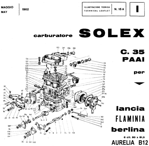
The SOLEX C.35-AAI Carburettor
Special Characteristics
Single Source of Air – The air required for float chamber ventilation, slow running & mixture emulsion, is all drawn from the carburettor main air intake & thus, is compelled to pass through the air cleaner.
The arrangement has the two-fold advantage of eliminating impurities & of rendering fuel consumption independent of air cleaner conditions of cleanliness, while keeping mixture richness constant.
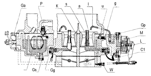
Key to diagram above
| See Fig. | Description | Size |
|---|---|---|
| a | Correction jet | 250 |
| B | Fuel | |
| C1 | Pump inlet valve | |
| F | Float | 8 gr. |
| g | Pilot jet | 45 |
| Ga | Starter air jet | 4 |
| Gg | Main jet | 140 |
| Gp | Pump jet | 200 |
| Gs | Starter petrol jet | 180 |
| l | Pump injector | |
| K | Choke tube | 26 |
| M | Pump membrane | |
| P | Needle valve | 1.75 |
| s | Emulsion tube | 3T |
| u | Idling air bleed | 100 |
| W | Volume control screw | |
| Accelerating Pump | No. 82 |
Starter – The starter ensures starting from cold, slow running from cold & driving away. It is used until the engine has reached its normal running temperature.
The starting mixture strength changes with the position of the dashboard control, the weakening of the mixtures is gradually obtained by progressively releasing the dashboard control.
Fully out (starting position), the mixture is very rich, & allows starting when the engine is cold.
Half way in this intermediate position is used when the engine is just warm, either after having run in the previous position, or when the engine has not become quite cold after stopping.
Accelerating Pump – The accelerating pump is of the standard type installed on Solex carburettors. The special feature of the pump on this carburettor is represented by the control, which is so designed, that the output fuel of pumping strokes, besides being adjustable in quantity, may also be injected during the rotation of the primary throttle alone, secondary throttle alone, or of both throttles simultaneously.
Connection for suction Ignition Advance – On the engines fitted with depression-operated ignition timing, connect the depression pipe to the tube provided on the throttle body of the carburettor


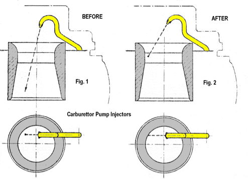
The following improvements have recently been brought in the SOLEX 35 PAAI carburettor of the Flaminia engine & apply to all cars in circulation:
- Replacement of the starter jet (230) with another of (180)
- Correction of the injector stream aim as shown in fig. 1 & fig. 2 above so that the stream of fuel hits the upper part of the choke tube instead of falling inside.

The following exploded parts diagram is taken from the Flaminia Spare Parts Catalogue by Lancia C. & is a different of, & differently numbered figure from that of SOLEX on page 01.7/19 above.


The WEBER 32 DR 7SP Carburettor


| 1 | Adjustment screws of economiser (E= summer, I = winter) | On top cover to be rotated so that the letter E or I corresponds to the fixed mark |
|---|---|---|
| 2 | Main jet | 1.25 mm |
| 3 | Adjustment screw of butterfly | |
| 4 | Slow-running adjustment screw | |
| 5 | Slow-running jet | 0.05 mm |
| Diffusers | 24 mm | |
| Compensating jet | 2.40 mm | |
| Starting device & economiser | Controlled by lever under dashboard: When pulled right forward = normal; half-way = economiser; right back = enricher |


The WEBER 40 DCF/DCL/DCZ 5 Carburettors
The Weber 40 DCF/DCL/DCZ 5 for the Aurelia B22, B24 & B20 from B20-2232 (Tav. 13bis SI & Tav. 14 SII)


| 1 | Idle running jet (to the opposite side the jet for the left hand cylinders | DCF; DCZ; DCL = 0.55 |
|---|---|---|
| 2 | Adjusting screw for starting device jet (I = winter; E = summer) | |
| 3 | Main jet (jet of left bank cylinders on the opposite side | DCF; DCZ = 1.40 DCL5 = 1.35 |
| 4 | Adjusting screw for idle running | |
| 5 | Throttle adjusting screw | |
| 6 | Throttle opening control lever | |
| 7 | Control for starting device | |
| Diffusers | DCF; DCZ = 26 DCL5 = 25 | |
| Compensating jet | DCF; DCZ; DCL = 1.60 | |
| Pump jet | DCF; DCZ = 0.80 DCL = 0.65 |
Note: The jet sizes have been taken from various Aurelia Instruction Books. The DCF information applied to the B20 Series 3; the DCZ was for a Series 4; the DCL was for Series 5 & 6. All numbers are in mm


