General Description - Series II
Series II Aurelias are defined by a new rear suspension introduced in 1954 consisting of wheel location by semi-elliptic leaf springs, De Dion tube with Panhard rod and telescopic dampers.
Arguments continue as to the benefits of this heavier system over the earlier one, but the Series II system does give a superior ride and at least as high cornering speeds, despite the fact that the B20 competition successes were accomplished with the Series I system.
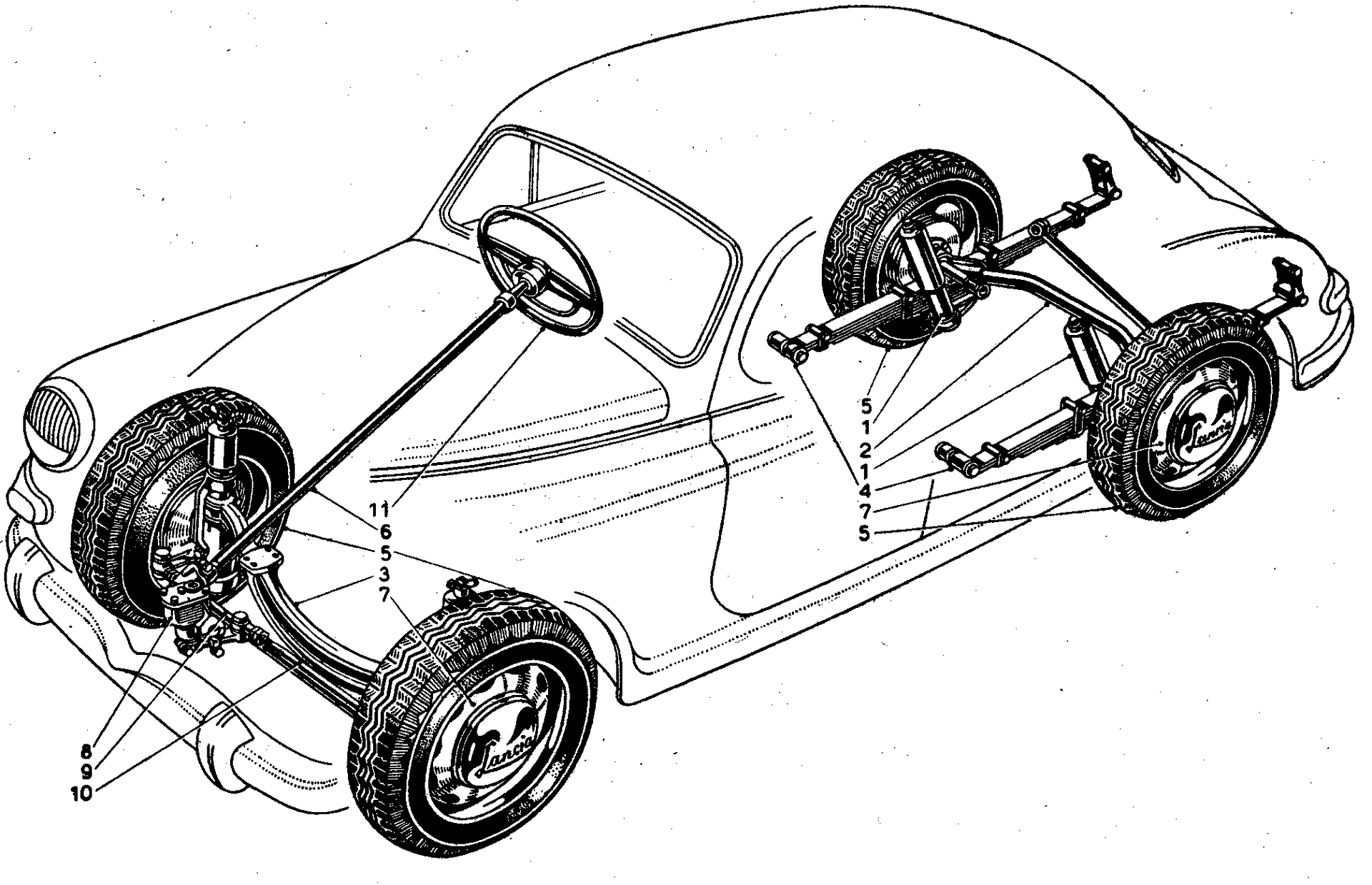
Tav.45 – Series II Rear Suspension
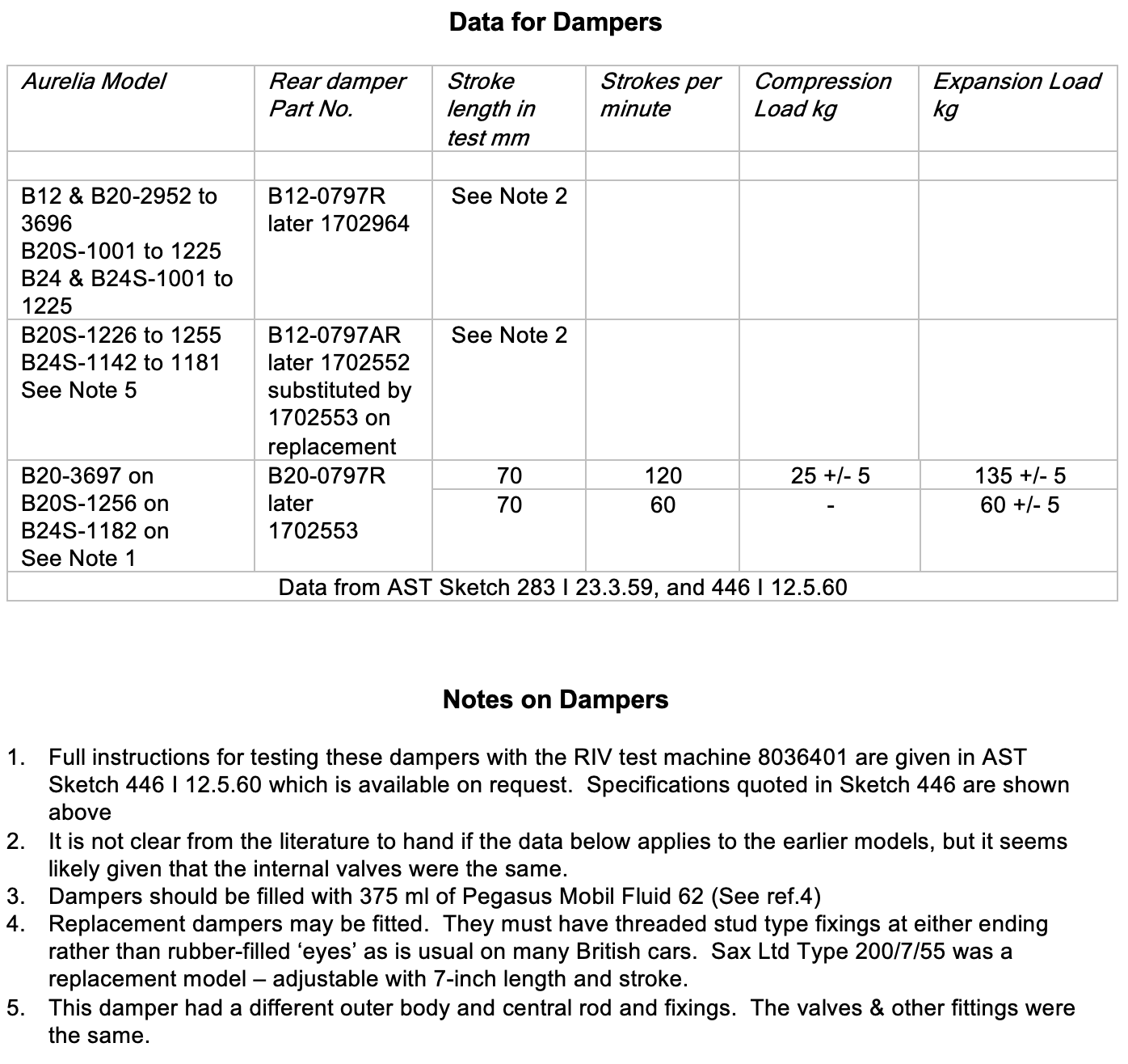
- Rear dampers (see above)
- Rear axle (De Dion tube)
- Front axle – See Front Springs
- Rear leaf springs
- Tyres
- Wheels
Leaf Springs
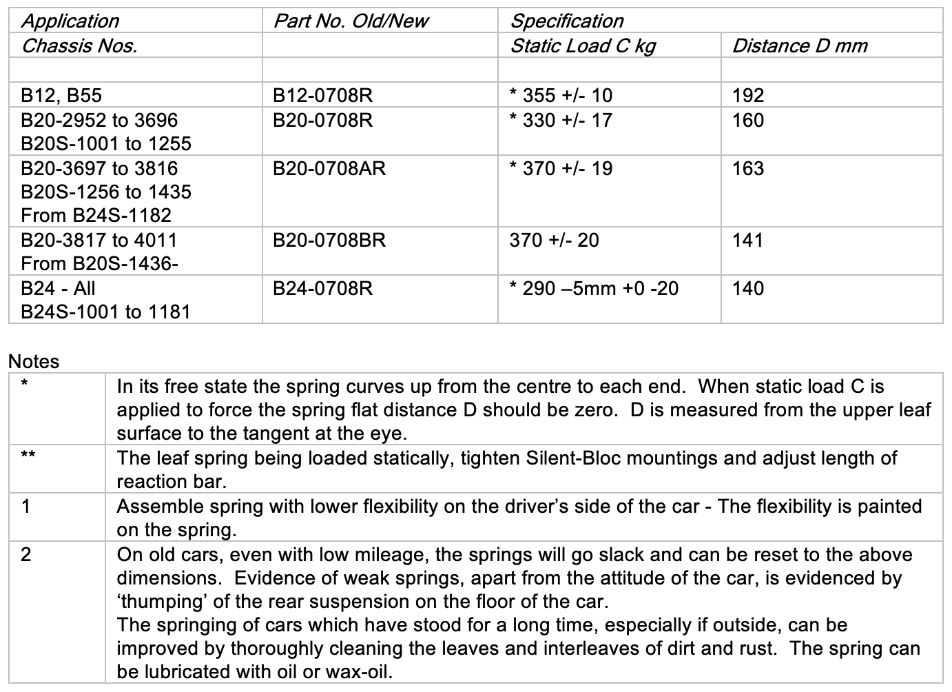
The leaf springs are mounted in Silent-Bloc bushes, one at the front and two at the rear. The 9 steel leaves are separated by rubber interleaves.
Spring specifications are as follows, adapted from Sketch 283I (23.3.59)

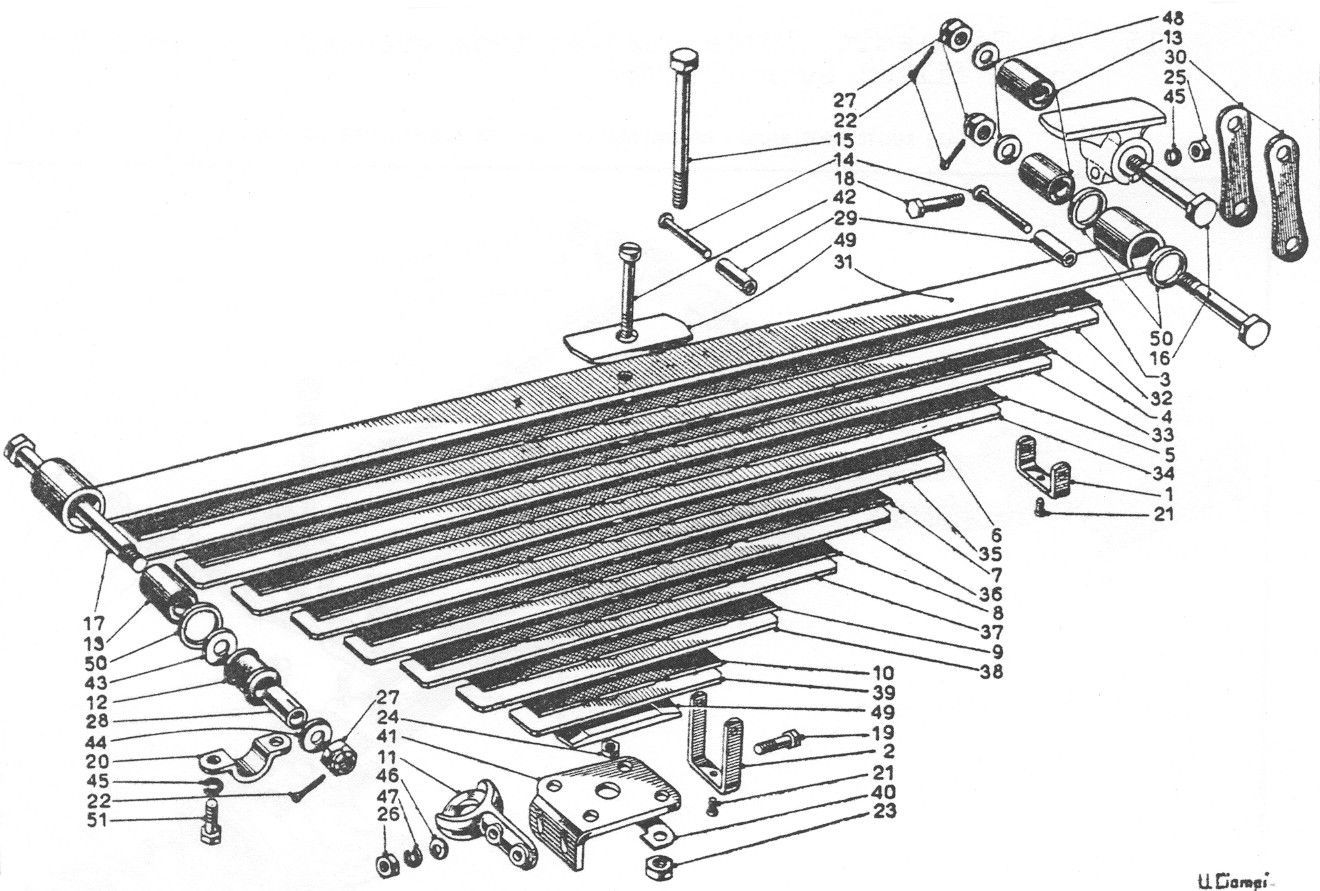
From Ref.6 Tav.54 SII
De Dion Tube and Panhard Rod
The De Dion tube or rear axle and the Panhard rod or reaction bar, are shown below with dimensions
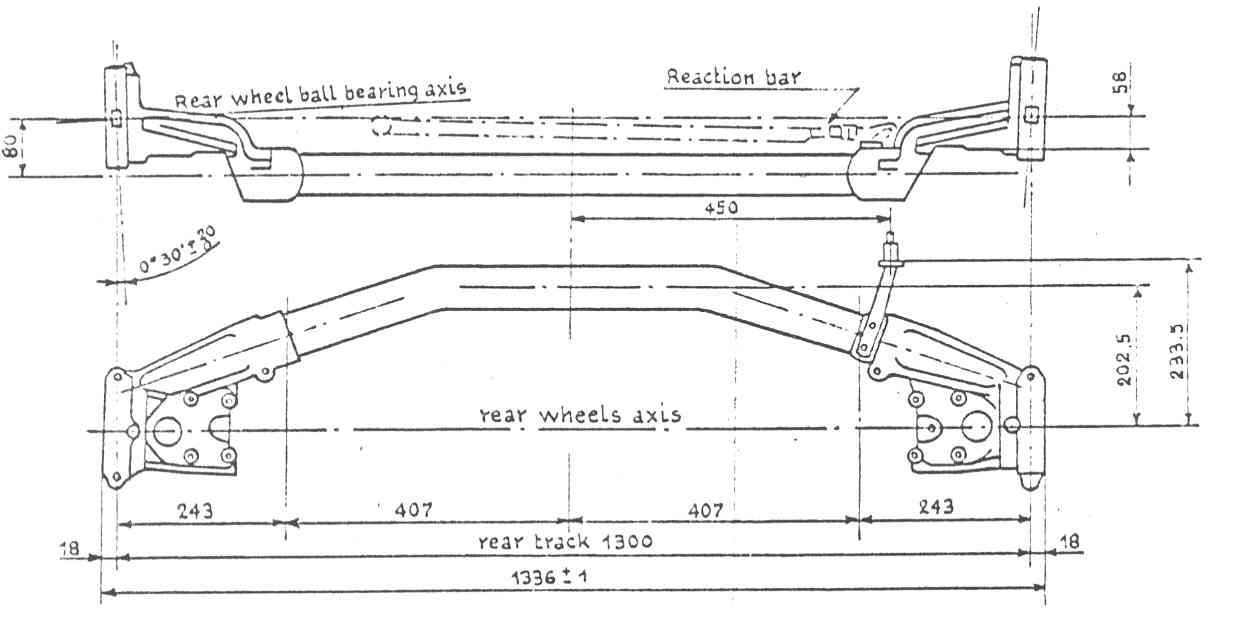
From AST Sketch 283 I 23.3.59
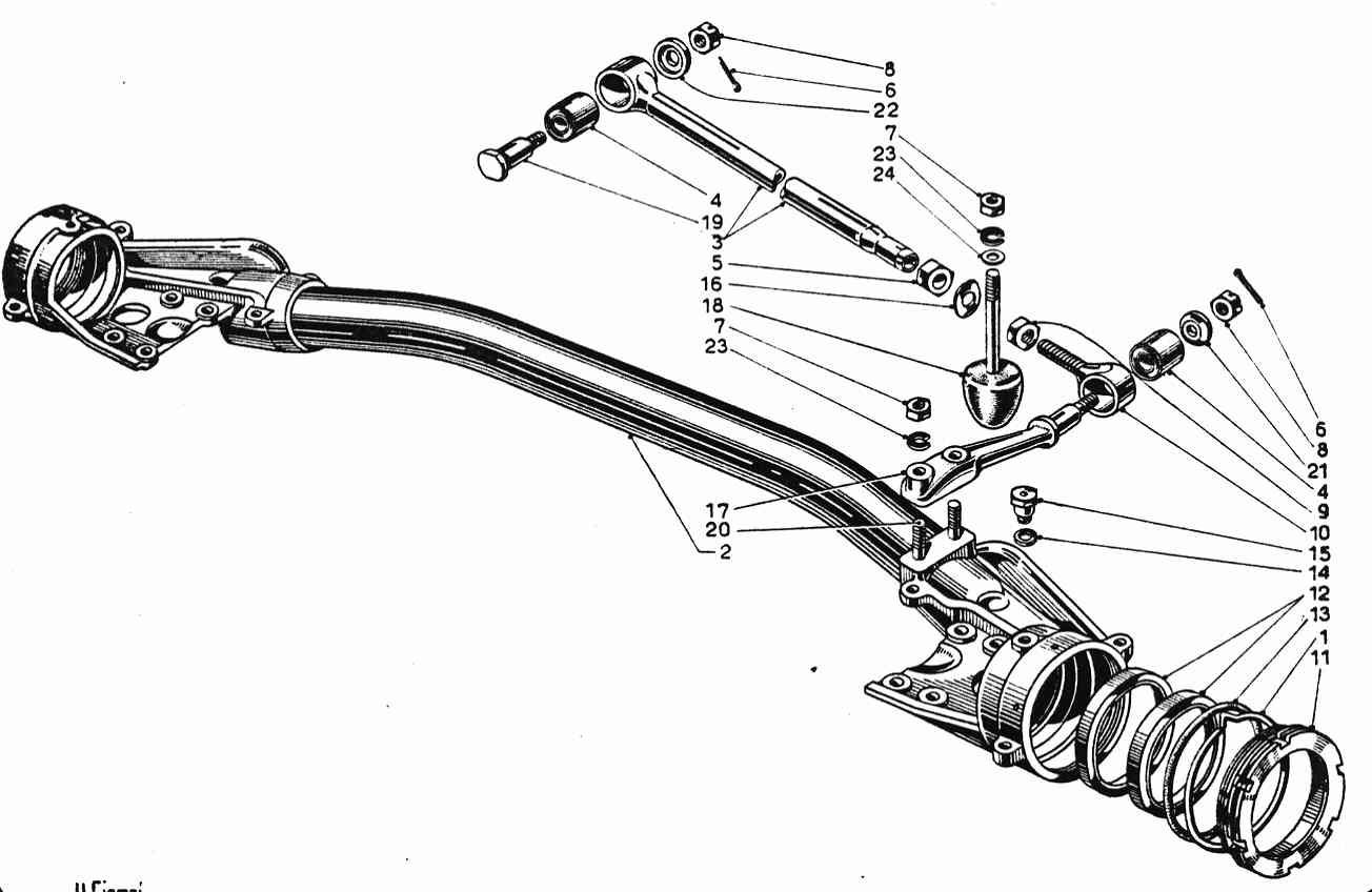
From Ref.6 Tav. 53 SII

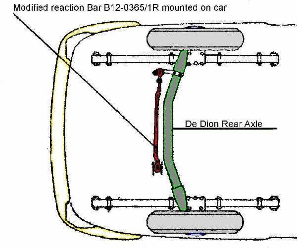
Front of Car
To fit modified Panhard Rod B12-0365/1R
The figure below shows the modified rod in place. Note that the convex side of the rod should be turned towards the rear of the vehicle (the original rod is straight as shown in Tav.53 above).
The modified rod should be adjusted to the same length as the old type, which was removed. For the exact adjustment refer to Sketch 283 above, so that the attitude of the rear axle is as shown when the rear springs are under static load.
Telescopic Damper or Shock Absorber
B12, B22, B20 Series 4 & B24 Spider
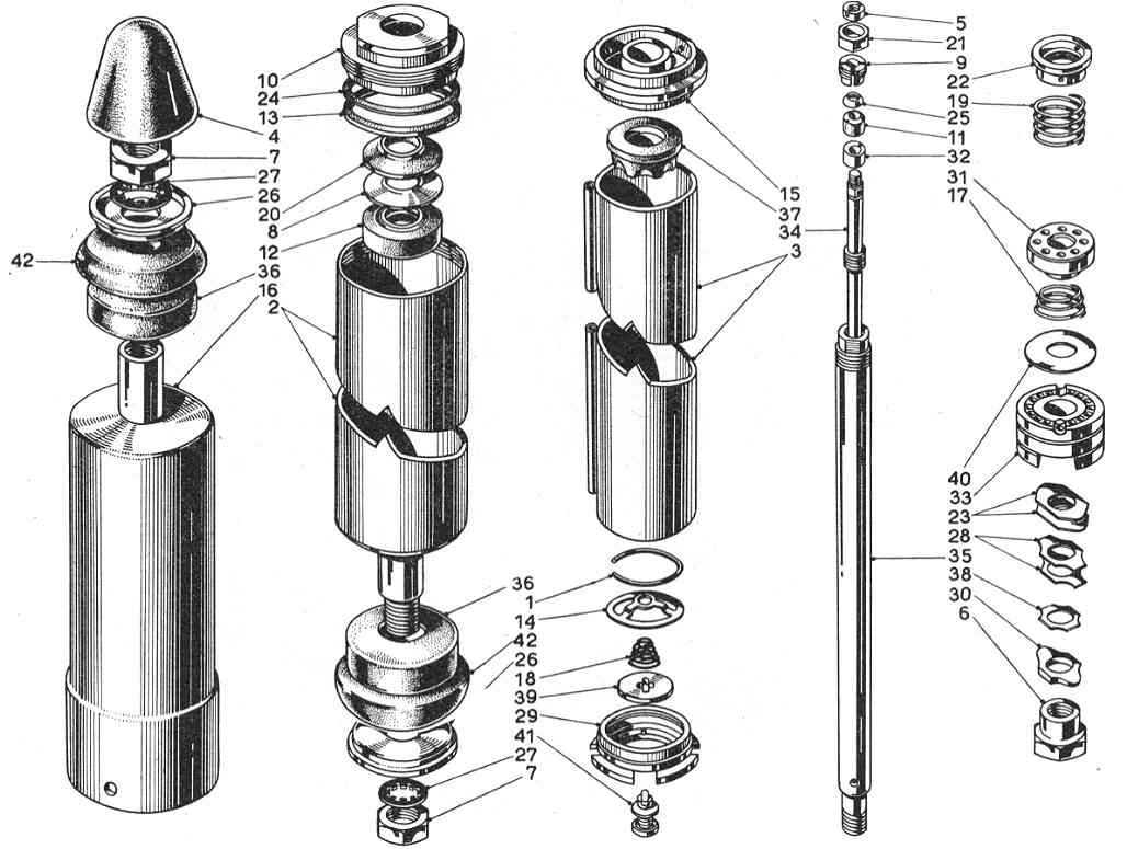
From Ref.6 Series II Tav.55
B20 Series 5 & 6, B24S Convertible
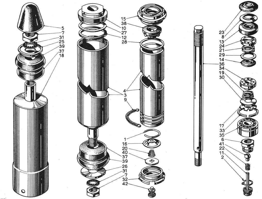
From Ref.6 Series II Tav.55 bis
The following types of damper were fitted, earlier types being adjustable. They were manufactured by SABIF.