Overhaul Instructions
Front Suspension Overhaul Instructions
The following text has been retyped from Lancia & C. Supplemento al Notizario N.8 – Ottobre 1955 Aurelia e Appia – Description, Maintenance and Overhaul of the Front Suspension. Details specific to the Appia have been eliminated. The diagrams & half-tone photographs have been scanned into the text. The tool numbers in the original text have been updated to seven figures with a prefixed 8, as used in the tool catalogues & in New Link below. This section includes descriptions & illustrations of all the tools.
Description
- The front suspension of the Aurelia cars, as shown in Fig. 2 is of the classic independent wheel type with vertical sliding action patented by Lancia, & is substantially the same as on previous cars, from which it differs only in certain improvements in detail.
- It consists essentially of a stub axle mounted on a tubular column pivot, on the outside of which is the cylindrical suspension spring, & inside, the hydraulic shock absorber, which can be adjusted & is damped hydraulically at the end of its movement.
- When a front wheel meets an obstacle &, in being forced upwards, compresses the suspension spring, the piston also moves upwards & presses on the fluid above it. This is compelled to pass through the openings in the piston rod & in the piston & so through the disc valve in the lower part of the shock absorber.
- During the movement the fluid meets with little resistance.
- When the wheel has passed the obstacle & the suspension spring, which was previously compressed, expands & pushes the wheel downwards into its original position, the piston is also forced downwards & compresses the fluid below it, obliging it to pass through the openings in the piston-rod & the piston & so through the laminated tongue valve into the upper part of the shock absorber.
- During this movement the fluid meets with a fair resistance, which may be regulated by the regulator needle (#12) which is controlled by the upper hand-lever (#1). When this is screwed or unscrewed the lower conical end either moves towards or recedes from the aperture in the central plug of the piston rod, thus regulating the supplementary passage of oil through the aperture.
- At either end of the movement there is a considerable & progressive increase in the resistance offered to the fluid owing to the fact that the openings in the upper & lower part of the piston rod are shut off in turn by the upper & lower piston-rod guides.
- This represents the hydraulic damping of the end of the suspension movement, which is completed by the elastic action of the rubber buffer.
- The upper part of the shock absorber contains a reservoir of fluid, which passes automatically into the shock absorber when any loss of fluid causes a lack of it in the shock absorber itself.
- The reservoir is kept supplied by means of a feed-tank under the bonnet to the right of the engine, the tank being supplied with an inlet piston & a three-way tap connected to the two suspensions by rubber tubing.
Maintenance
- Maintenance is very simple & requires no special treatment. Topping up with fluid needs doing only when the suspensions tend to become noisy owing to inevitable losses of fluid. It is carried out by acting on the pommel of the feed-tank according to the instructions on the tank itself.
- The fluid inserted also serves to lubricate the sliding upper parts of the suspension.
- The fluid to be used is either Veedol HD Plus 20-30 or Mobiloil Arctic
- Lubrication of the sliding lower parts of the suspension is done through a special lubricating plug situated in the rear part of the stub axle, or, in the case of cars without this plug, by filling the lower suspension plug, which should be unscrewed with spanner 8041134.
- The oil used for lubricating the lower parts is Veedol HD Plus 40 or Mobiloil AF.
- As mentioned in the description above, the suspension firmness is regulated by a hand-lever at the top of the assembly (#1 Fig.2). This is screwed tight until the regulator needle closes the internal oil passage & then unscrewed from ½ to 1 ½ turns in summer, & from 1 ½ to 2 ½ turns in winter.
- NB: For cars with chassis numbers up to B12-1870, B12S-1569, B20-3454 & B20S-1135, which have a regulator needle with a smaller conical end & the aperture of the central plug of smaller diameter, the above adjustments should be increased to 1 to 2 turns in summer, & 2 to 3 turns in winter.
Overhauling - Dismantling Front Suspension
- Remove the front axle from the vehicle, after first disconnecting the flexible hydraulic brake pipes from the upper end attached to the chassis, the feed tubes from the inlet union on the suspension & the drag link from the steering drop-arm.
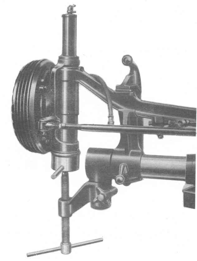
- Mount the axle on the trestle jig, Tool no. 8037001, as shown in Figure 1, & proceed with the dismantling in the order given below, taking care that every part, & especially moving parts which have worn together during operation, may be reassembled in its original position.
- Remove the drag link & the track rod with spanner 8061001.
- Place a receptacle under the axle to the collect the oil. Unscrew the bottom guide (#25), complete with plug (#26) using spanner 8041135, kept against the guide by means of the screw of the appropriate arm of the trestle jig, at the same time loosening the screw underneath. When the suspension is free withdraw the bottom guide & the relative internal parts.
- NB: When dismounting the bottom guide for repairs which can be carried out without removing the front axle, spanner 8041135 must be used with support 8043107, set up for the purpose on the floor.
- If necessary for checking or overhaul, unscrew the plug of the bottom guide with spanner 8041134.
- After first removing the screw that holds it, dismount the shock absorber adjustment hand lever (#1)
- Using a 17 mm fixed spanner, loosen the inlet union screw (#2) & remove the union (#3) & the gasket washers.
- Unscrew the top guide (#4) with spanner 8041112. For cars up to chassis number B10-2902, B50-1410 & B51-1073, before this operation the top guide housing must be removed.
- Pull up the loosened cover together with the piston rod, & keeping this engaged in the appropriate flats with a fixed 11 mm spanner, unscrew the cover (#4) from the piston rod.
- For cars up to chassis number B10-2902, B50-1410 & B51-1073, extract the spring retainer & the dust protector ring with a screwdriver from their seating in the top guide.
- Remove the stub axle, brake & wheel hub unit by withdrawing it from the top part of the suspension column (#14).
- The removal of the top guide (#13) from the stub axle is only necessary when, in checking, it is found to require replacing (use spanner 8041134).
- Remove the top buffer pad (#6) using spanner 8041132.
- Remove the top end of the suspension column (#7) & the gasket (#10) &, for cars up to chassis number B10-2902, B50-1410 & B51-1073, take off the spring retaining ring & the dust protector ring, which have been previously extracted from their seating.
- Unscrewing it with spanner 8041138, remove the top guide ring (#9) & extract the piston rod (#5) complete with shock absorber piston (#16), with which the top guide of the piston rod itself will also be extracted.
- Turn the axle over & then take off the rubber bottom buffer (#23) & unscrewing it with spanner 8041136, remove the plug of the bottom suspension column (#22) & its washer.
- Using spanner 8041137 remove the bottom end of the suspension column (#21) & its washer
The Factory Tool, sadly no longer available to most of us.
Checking Dismantled Parts
- Having completely dismantled the suspension as above, wash & clean all the parts thoroughly in paraffin & check carefully as follows:
- See that there is not too much clearance between the top & bottom ends & the guides, & that their touching surfaces are not scratched or worn irregularly.
- Check that there is no endplay in the shock absorber piston due to looseness of the fixing nut using spanner 8041141 for nut (#18) with holes or a 19 mm spanner for a hexagonal nut.
- Check the disc & the tongued laminations of the valves in the shock absorber piston & the oil recovery valve in the top piston rod guide. Make sure that they have not lost their elasticity or become broken, & that there are no foreign bodies between them & their respective seating, causing an imperfect seal.
- Check that the lower spherical valve of the piston rod is in working order & is clean.
- Check that the transverse hole in the shock absorber piston coincides exactly with the hole in the piston rod, which is essential to avoid blockage of the oil passage & therefore in the regular functioning of the shock absorber. (In Figure 2 the transverse hole is only partly visible as the section of the piston in shown in two planes.)
- For the first series of Aurelias & up to B20-2951, which have a disc instead of a spring valve support, and a hexagonal nut instead of one with holes, the alignment of the piston and the piston rod holes and the exact position of the incisions of the valve support with respect to the axial holes of the piston, are obtained by using special tool 8043103.
- Check that the washers of the shock absorber regulator needle (#12) and the inside of the piston rod grip tightly. If the regulator needle has to be replaced, remember that the new part is delivered with the diameter of the sealing washers slightly increased, so that to avoid excessive forcing in mounting, it is necessary to go over the washers with a smooth-cutting file taking care not to produce ovalities.
- Check that the gasket at the upper end of the suspension column (#10) grips firmly.
- Check the threaded seatings, upper and lower, of the stub axle and the suspension column (#14), as well as the seating of the piston rod guide on the suspension column itself. If necessary they should be gone over with the following tools:
- Tool 8044110 with tap for the upper threaded seating of the stub axle.
- Tool 8044112 with tap for the lower threaded seating.
- Tap 8044102 for the upper threaded seating of the suspension column, and tap 8044109 for the lower threaded seating using the guide mandrel 8044108.
- Cutter 8044100 for the seating of the top piston rod guide, using the guide mandrel 8044108.
- If from the above checks there are parts, which show excessive, wear or deterioration they should be replaced.
Reassembly of the Front Suspension
- After checking the squaring of the axle (gauge 8045003) and the inclination of the columns (gauge 8045005) on the checking plane, remount the axle on the trestle jig 8037001.
- Smear the threaded porting of the bottom end (#21) with a mixture of lead oxide and oil, and screw it in with spanner 8041137, taking care to insert the respective sealing washer.
- Assemble the bottom end suspension column plug (#22) with its washer (spanner 8041136) and fit on to it the lower rubber buffer pad (#23).
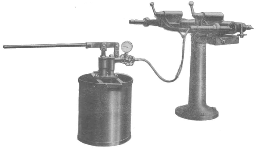
- At this point place the axle with columns (#14) in a horizontal position &, to avoid oil losses when the suspension is completely assembled, give a hydraulic pressure test using apparatus 8045102 & tool 8045100, as shown in Figure 3. The test must be carried out at a pressure of 45 kg/cm².
- If as a result of this test oil losses are discovered from the suspension column, the latter must be replaced as described in the following section ' Replacing the Suspension Column on the Axle'.

- Upper hand lever
- Inlet union screw
- Union
- Top guide
- Piston rod
- Top buffer pad
- Top end of suspension column
- Washers
- Top guide ring
- Gasket
- Top piston guide rod
- Regulator needle
- Top guide
- Suspension column
- Retaining dowel from axle to suspension column
- Shock absorber piston
- Bearing
- Nut - may have holes or 19 mm head
- Top housing for suspension spring
- Suspension spring
- Bottom end of suspension column
- Plug of bottom suspension column
- Rubber bottom buffer
- Lower oil plug
- Bottom guide
- Bottom guide plug
Replacing the Suspension Column on the Axle
- Unscrew & extract the retaining dowel of the suspension column from the axle (#15), then withdraw the suspension column with a hand press.
- Heat the end of the axle by immersing it in oil at a temperature of 120° to 150°C (250°F to 300°F.) for about 15 minutes.
- Carefully clean the outer surface of the new suspension column & smear about 50 mm of the central part with beef suet to avoid sticking during coupling.
- Remove the axle from the oil bath & connect the suspension column rapidly by means of the hand press using tool 8042002 & distance piece 8042008.
- With a 4.5 mm twist drill directed into the seating of the retaining cylinder on the axle, make a dead hole in the suspension column to a maximum depth of 2 mm. This depth must be scrupulously observed!
- Fix the suspension on to the axle, remounting the retaining dowel (#15).
- Replace the axle in its original position.
Fitting the Upper, Damper Section of the Sliding Pillar
- Insert the complete piston rod (#5) & at the same time the top piston rod guide (#11) into the suspension column.
- Mount the top guide ring (#9), screwing it in with spanner 8041138.
- Check that the piston rod slides & turns freely.
- Unscrew the ring (#9) & re-extract the piston rod with its guide, fill two thirds of the suspension column with the prescribed oil.
- Remount the complete piston rod on the suspension column & push it well down, thus causing the passage of the oil into the upper part through the piston & the piston rod.
- Then insert the piston rod guide (#11) in the suspension column, taking care to keep the valve on the guide slightly open by means of the tool 8043102 to allow the air & oil to escape.
- Screw up & tighten the top guide ring (#9) with spanner 8041138.
- For cars up to chassis number B10-2902, B50-1410 & B51-1073, slip the spring retaining ring & the dust protector ring onto the suspension column.
- Fit the gasket (#10) & with tool 8042106 the top end (#7) onto the suspension column.
- Smear the threaded portion of the top buffer pad (#6) with a mixture of lead oxide & oil, then after inserting the washers (#8), which should be divergent, screw it up & tighten with spanner 8041132.
- [1] Notizario n.8 typed up with scans of Figures 23rd July 2007 [2] Mods re Styles 6.08.2007; [3] Rearranged text, to Font 10, Styles checked 8 Feb 2019;
- Fill up with the prescribed oil to the top level of the buffer pad (#6).
- Mount the stub axle, brake & wheel hub unit. Before carrying out this operation check the alignment of the two eyes of the stub axle with mandrel 8045104, by provisionally mounting the bottom guide.
- Pull up the piston rod & keeping it firm with an 11 mm fixed spanner inserted in the flats provided, screw the top guide cover (#4) on to it with spanner 8041112.
- Smear the threaded portion of the cover with a mixture of lead oxide & oil & screw it on to the top guide with spanner 8041112.
- For cars up to chassis number B10-2902, B50-1410 & B51-1073 fit the dust protector ring & the spring retaining ring (previously slipped on to the suspension column) into their proper seatings on the top guide.
Fitting the Lower, Spring Section of the Sliding Pillar
1) Fit the top housing (#19) for the suspension spring on to the axle.
2) Mount the bearing (#17), with its seating & the suspension spring (#20) with the bevelled end facing downwards (on the Aurelia cars of the first series & up to car B20-2701, the bearing is mounted under the spring instead of above it).
3) After smearing the threaded portion of the bottom guide (#25) with a mixture of lead oxide & oil, fit spanner 8041135 on to it, & using the screw on the appropriate arm of the trestle jig compress the spring until the guide engages the threaded seating on the stub axle, then screw the guide itself up tight.
4) If it has been dismounted, remount the bottom guide plug (#26) with its sealing washer using spanner 8041134.
Final Checks & Assembly
1) After checking for regular functioning, mount the inlet union (#3) with its gaskets & screw (#2) using a 17mm spanner.
2) Mount & tighten the shock absorber adjustment hand lever with its screw (#1).
3) Unscrew the plug (#24) in the lower part of the stub axle & fill with the prescribed oil to the level of the filling hole, and then screw the plug up again. For cars without this plug fill the lower suspension plug (#26) with oil.
4) Reassemble the drag link & the trackrod, using spanner 8061001.
5) Remount the axle onto the car; reconnect the suspensions to the feed tank with the rubber tubing, the hydraulic brake tubes to their unions & the drag link to the steering drop-arm.
6) Adjust the suspensions using the upper hand lever as described above under “Maintenance”.
7) Bleed & refill the hydraulic brakes.