Brake Shoes
| General – See also Tavs. 43 in 'Brake Drums' | A variety of brake shoes were fitted, especially at the front. On each wheel, front & rear, the left & right shoes were slightly different except for the B20/B24 5th & 6th series front shoes. Nearly all shoes are alloy castings. On some later cars the trailing shoes are steel with an open web structure. This combination is for economy and heat dissipation, perhaps also for dynamic reasons. The pivot bolts & the bushings they go through in the shoes are all subject to wear & should be replaced or refurbished if worn. This is another possible source of the dreaded brake judder. |
|---|---|
| Aurelia 1950/52 B10, B21, B52 & B53, B50 & B51 B20 1st Series | These early saloons,& the B20 1st series cars, had 60 mm wide shoes & linings. The parts are thus not interchangeable with later cars. Front brakes (right/left): See SI Tav. 42 #3, #4 Forward shoes = B10-0641R/B10-0643R The parts were changed on late B10, B52 & B53 for the forward shoes only. The change seems to involve the pin #1 over which the return spring #13 fits. The new parts could be used on earlier cars: Forward shoes = B10-0641AR/B10-0643AR Rearward shoes = B10-0645R/B10-0647R Rear brakes (right/left): See SI Tav. 43 #4 #5 Forward shoes = B10-0341R/B10-0343R The parts were changed on late B10, B52 & B53 for the forward shoes only for the same reason as above: Forward shoes = B10-0341AR/B10-0343AR Rearward shoes = B10-0345R/B10-0347R |
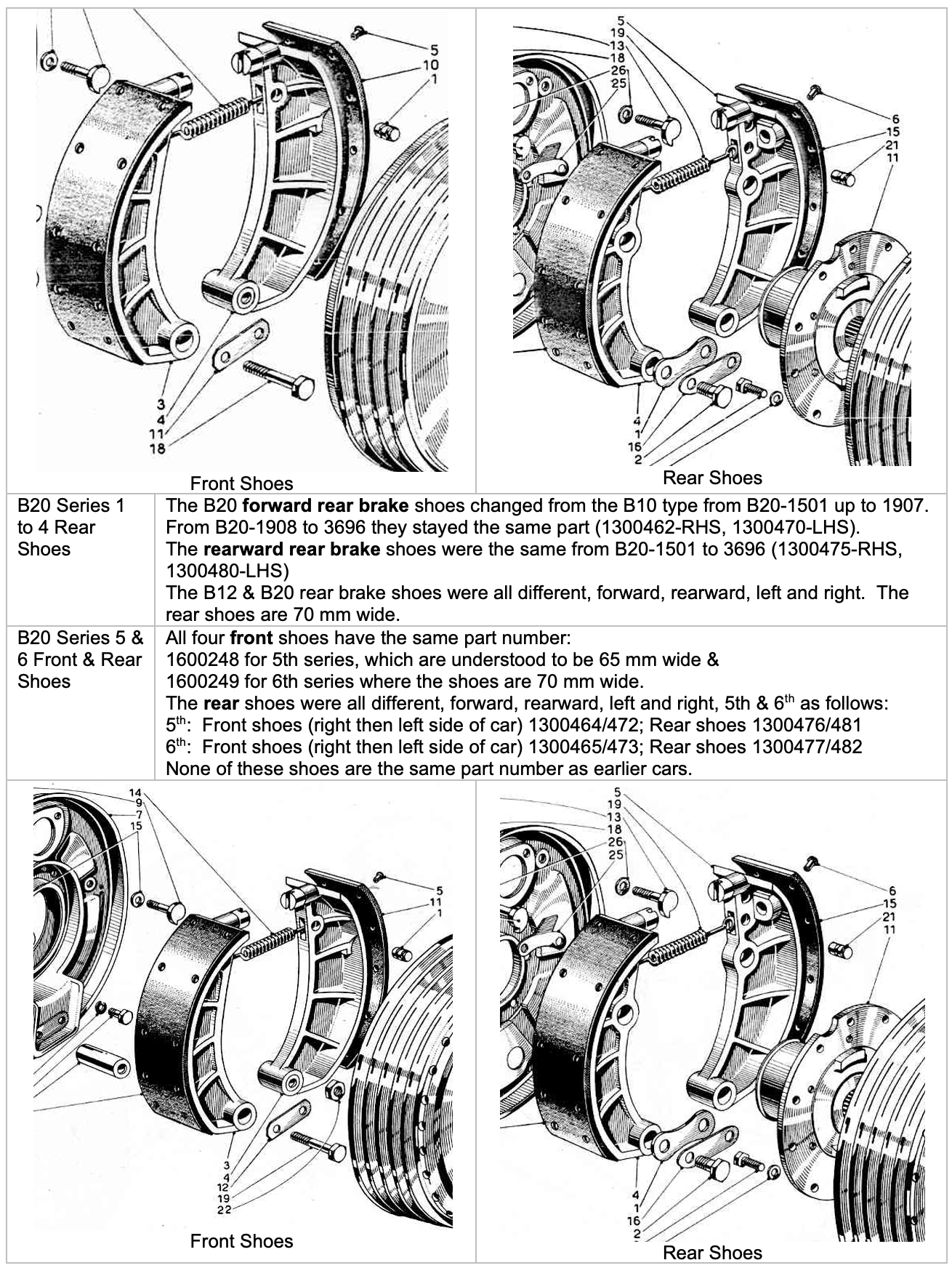
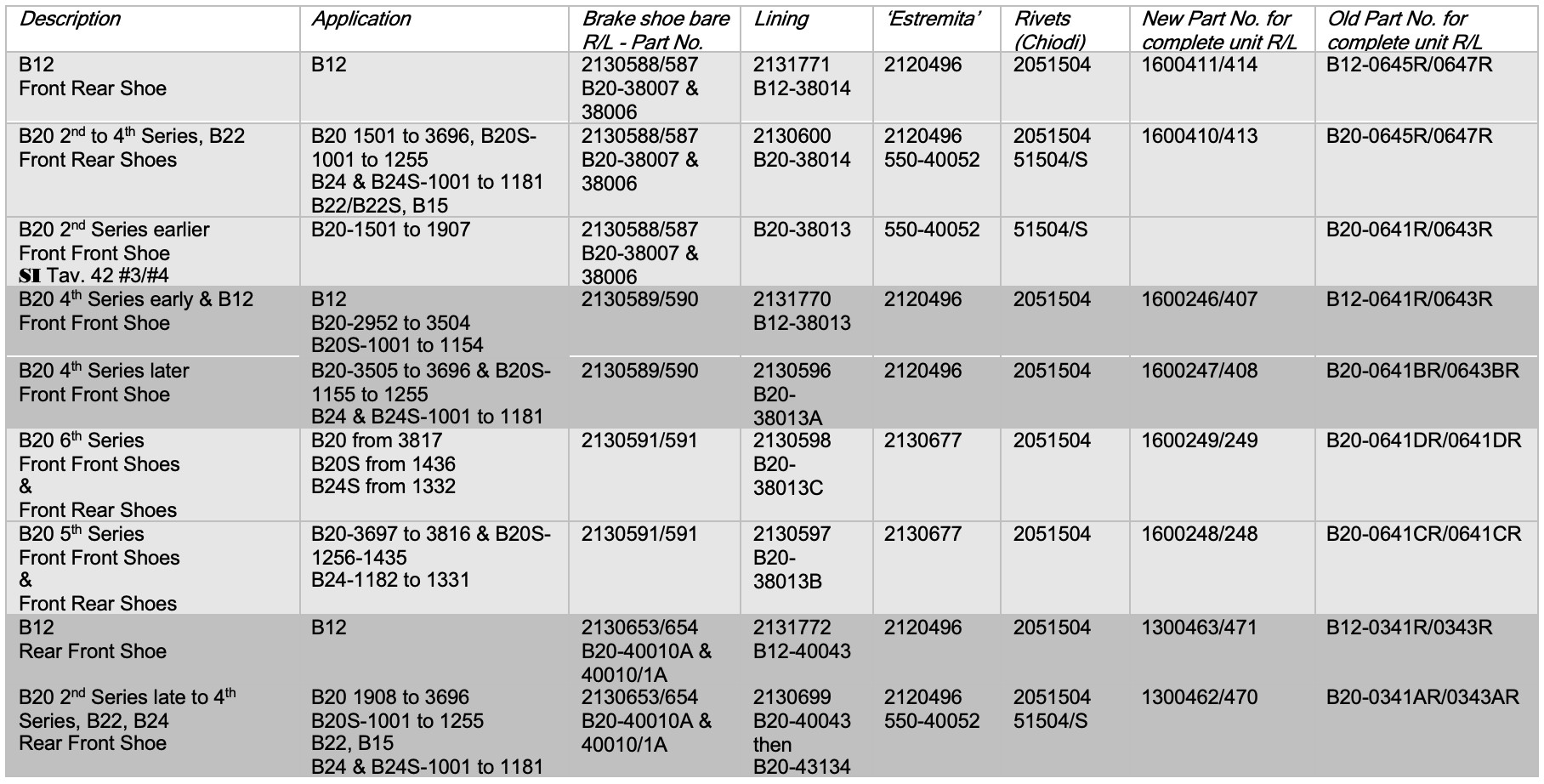
| B20-1501 to 1907 Earlier 2nd Series | 70 mm wide brake shoes were introduced & all parts were prefixed B20 rather than B10. Front brakes (right/left): See SI Tav. 42 #3, #4 Forward shoes = B20-0641R/B20-0643R Rearward shoes = B20-0645R/B20-0647R later numbers 1600410/1600413 & used on later cars. Rear brakes (right/left): See SI Tav. 43 #4, #5 Forward shoes = B20-0341R/B20-0343R Rearward shoes = B20-0345R/B20-0347R later numbers 1300475/1300480 & used on later cars. |
| B12 | The B12 had 70 mm wide shoes & linings but all the shoe part numbers are different from earlier & later cars with B12 prefixes in the older numbering system. Front brakes (right/left): Forward shoes = 1600246/407 (B12-0641R/B12-0643R) Rearward shoes = 1600411/414 (B12-0645R/B12-0647R) Rear brakes (right/left): Forward shoes = 1300463/471 (B12-0341R/B12-0343R) Rearward shoes = 1300478/483 (B12-0345R/B12-0347R) |
| B22, B15 & B20-1908 to 3504. Late Series 2 to mid-Series 4 Front Brakes | These cars also had 70 mm wide shoes. The forward front shoes changed from the B10-type at B20-1501 up to 1907, when they changed again from 1908 up to 2951. The B12-types were fitted from B20-2952 to 3504 when they changed yet again from B20-3505 to B20-3696. The parts book shows that rearward front shoes were the same from B20-1501 to 3696 (parts 1600410 (B20-0645R) - RHS, 1600413 (B20-0647R - LHS) and were not the same part as on a B10 or B12. The aluminium 4th series shoes are 70 mm wide & 300 mm long. |
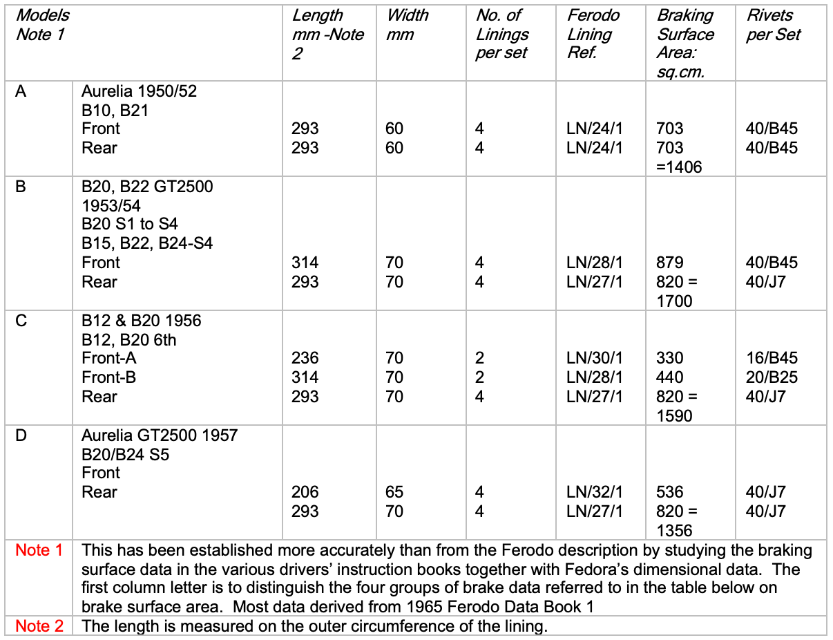
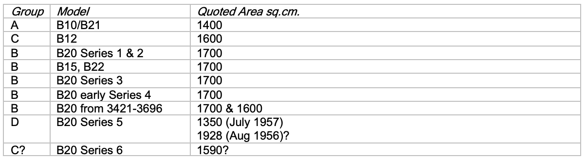
Types of Shoe seem to have been fitted to the Aurelia cars
Brake Linings
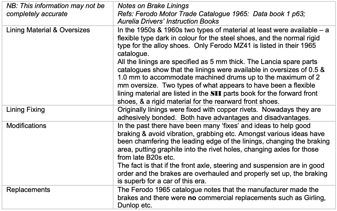
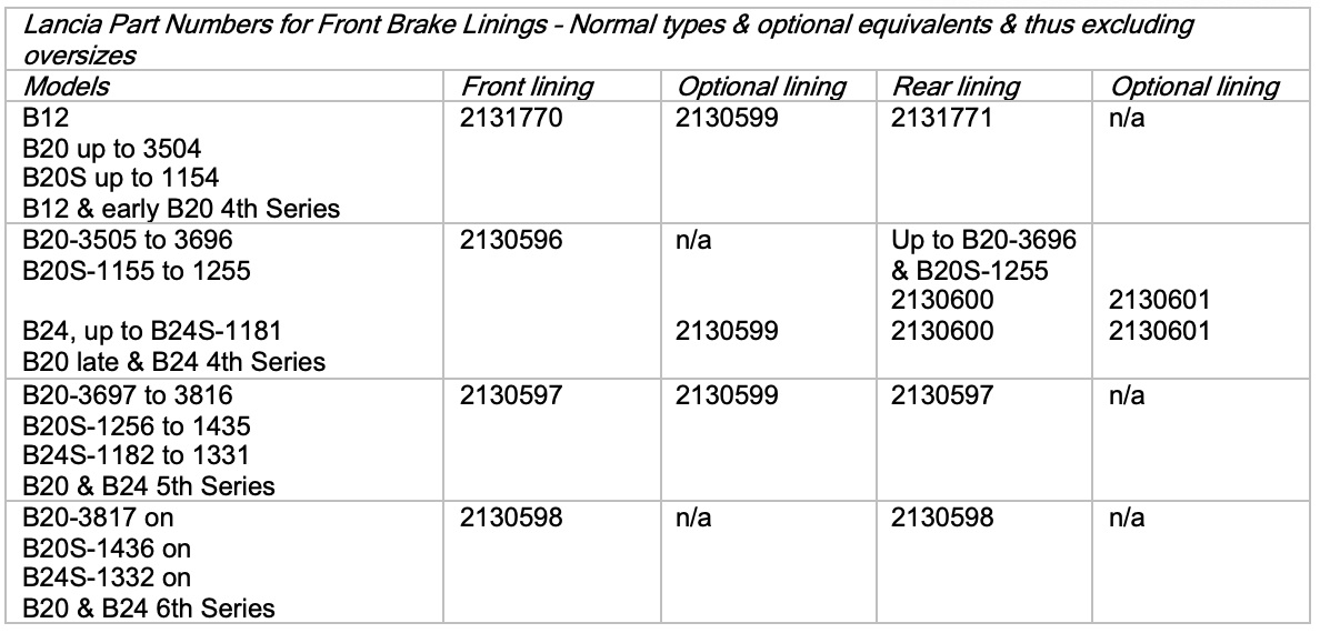
Brake Linings
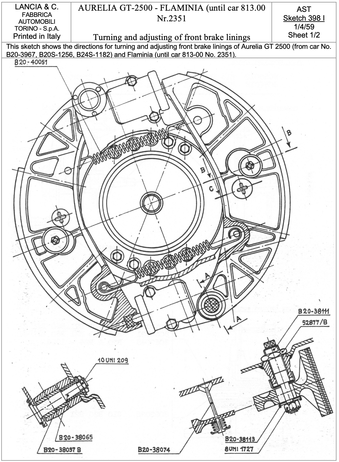
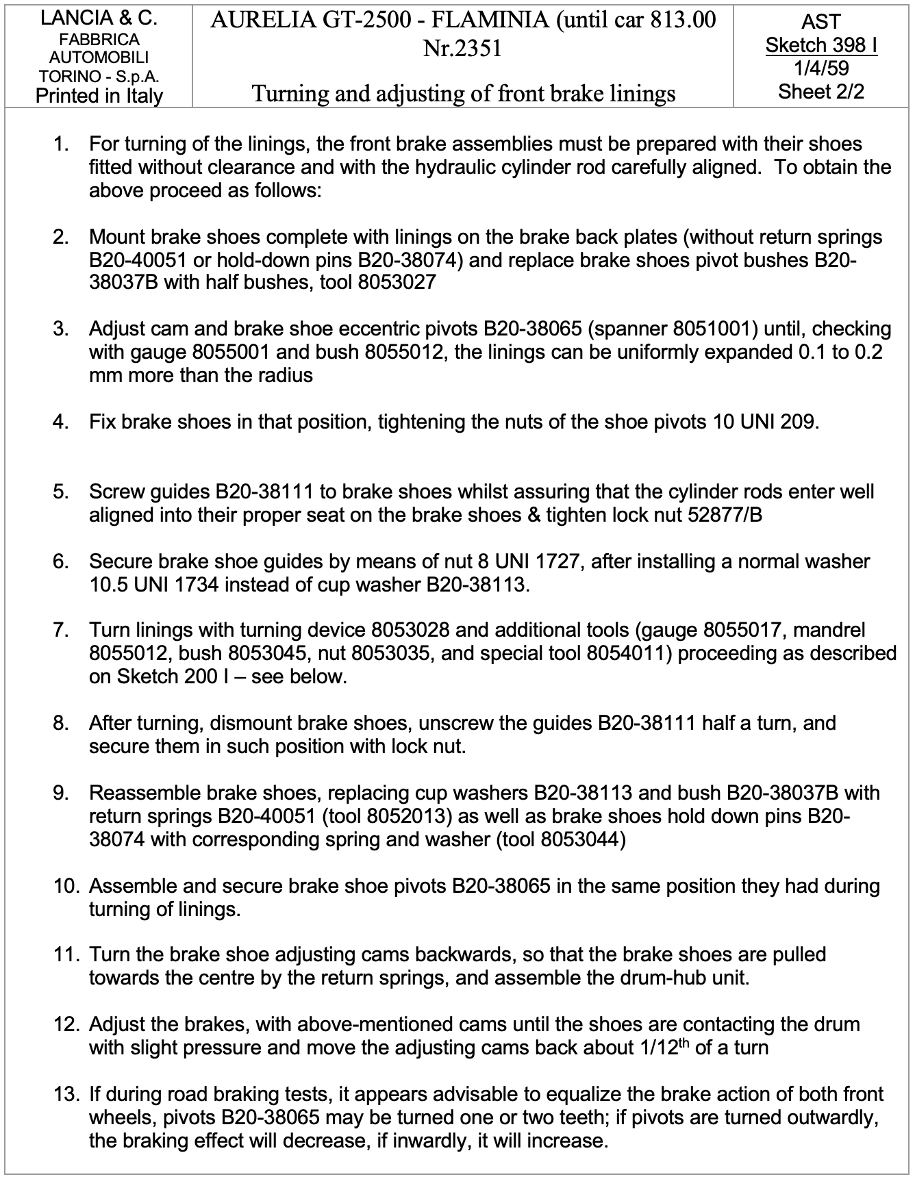
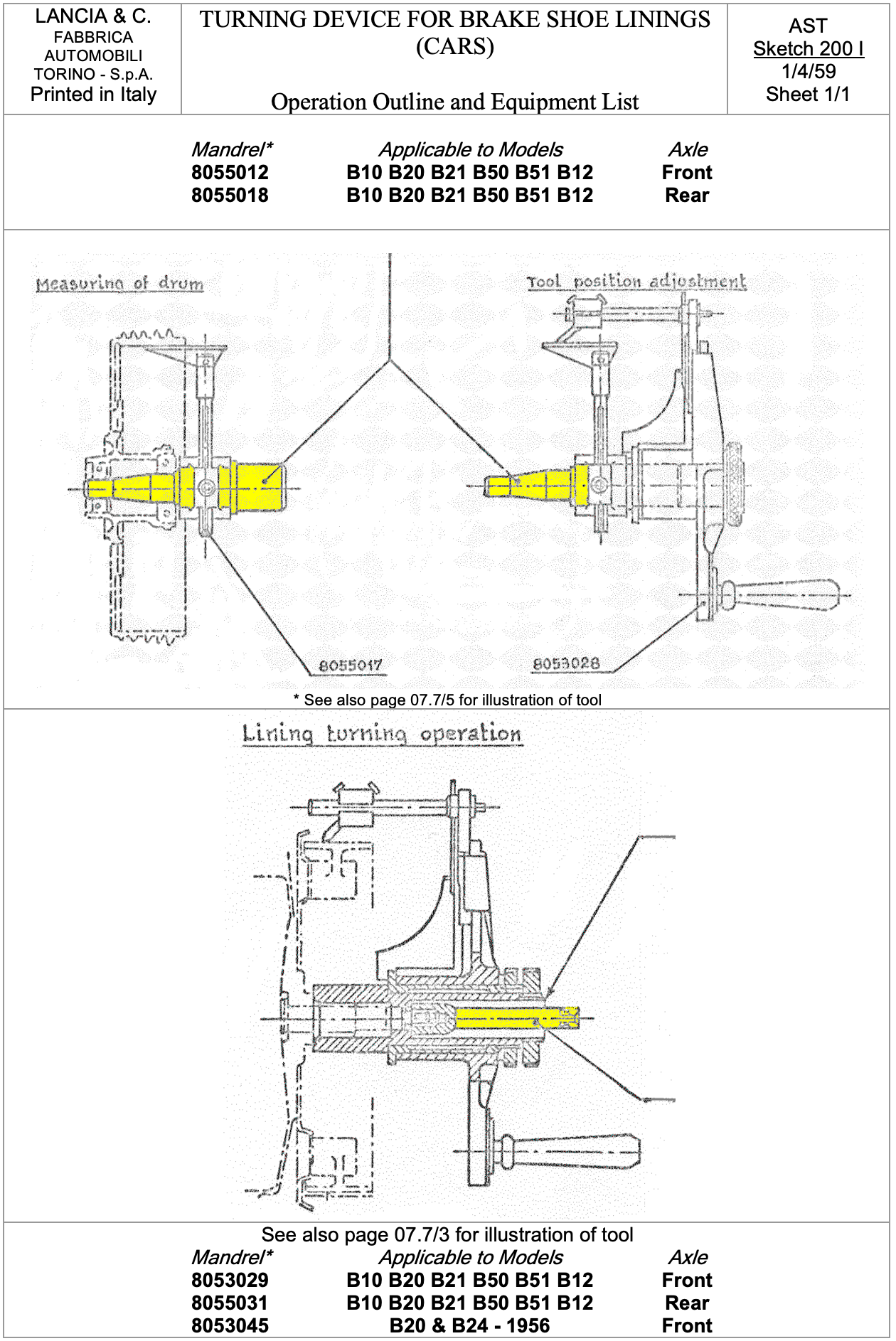
The following data is taken from AST Sketches 398 I and 200 I which describe the setting up for turning and the turning tool and procedure respectively. An article by Brian Long on the same procedure for late Series II cars completes this section.
Late Series Brake Adjustment by Brian Long
Published in Australian Lancia Register Newsletter No. 38, November 1980 & Lancia Motor Club (UK) Journal, Summer 1985. Retyped by Paul Mayo with minor editorial changes, March 2007
The factory instruction sheet 398 I, has a very good drawing of the front brake assembly, but it gives no instructions on setting it up {this is not strictly so as sheet 2 of Sketch 398 does have brief instructions as shown above, but Brian Long describes the method well & in detail – Paul Mayo}.
- I used the following procedure with excellent results after having had new linings fitted, the drums ground and the new linings sanded to the same effective diameter as the drums.
- Assemble the shoes to the backing plate complete with all springs, pistons rods etc. With the drum on, and largely by feel, adjust the eccentric cams and the snail cams until the shoes are bearing firmly against the drum.
- Then adjust the square-headed stud that bears on the web of the shoes (part B20-38111 on Sheet 398). This stud should be run in until resistance is felt. Lock it at this point and it thereafter keeps the shoes parallel to the drum.
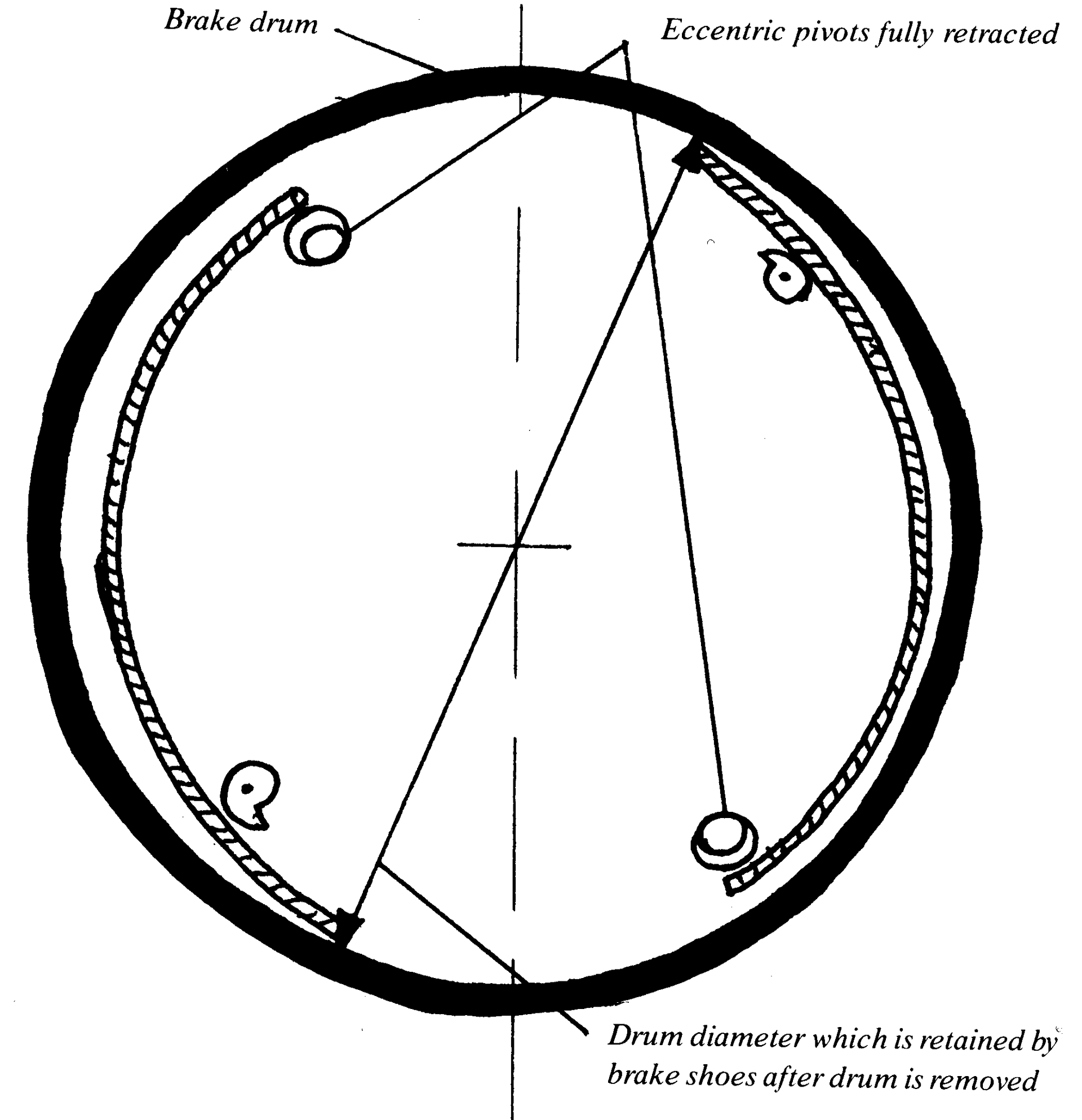
- Now set the eccentric pivots to a point that retracts each of the shoes fully away from the drum.
- Refit the drum and carefully adjust the snail cams until the shoes are just touching the cam. Note that on the RH wheel the cams are turned to the rear of the car to remove the shoes outward. On the LH wheel turn the cams forward.
- With the shoes now touching the drum at one place each (see diagram), the drum can be removed again, and the shoes at that one point each will retain the effective inner diameter of the drum.
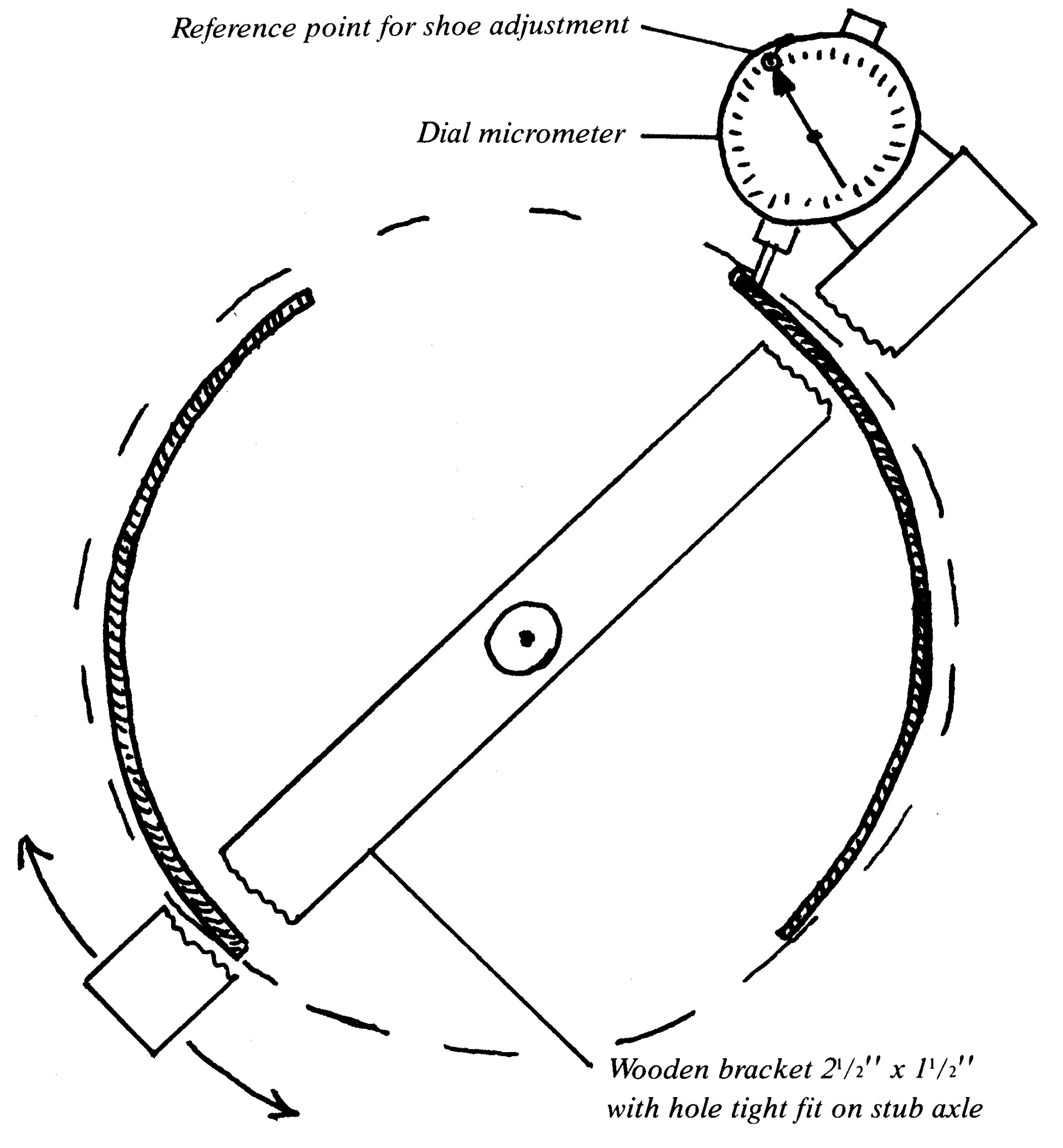
7. We now have to adjust both the cams and the eccentrics to get this effective diameter over the whole face of the shoes. I used a piece of timber with 18 inch long and 2.5 inch by 1.5 inch (otherwise about 450 mm long & 65 x 40 mm) and with a spade bit drilled a hole to make a snug fit on the stub axles. This piece of wood must be long enough to bear on the outer sides of the shoes, which will steady it.
8. Mount a dial micrometer on one end of the timber so that its probe bears approximately in the centre of the shoe’s width.
9. Set the micrometer at the point of maximum diameter and zero it. If you now move the timber around you will see the micrometer registering the fact that the shoe is at a lesser and lesser diameter as you move from the maximum diameter point.
10. By adjusting the eccentric and snail cams you will be able to get the micrometer measuring virtually nil deflection from the reference point when the shoes are set correctly, provided the shoes have been ground to the same diameter as the drum.
11. Lock the eccentrics in place and back off the snail cam. Once the drums are back on, adjust only the snail cam approximately 1/8th turn back from where the shoes just touch the drum.
12. Having used this procedure I could do ‘hands off’ panic stops, on a deserted road, without the car pulling in either direction at all. The important point is that the procedure relies on the drum and shoes being of matched diameters. Most brake shops have a finishing belt machine that dresses linings to the diameter of the drum.
13. A further note of caution: on the B12 and earlier B20s with leading/trailing front brakes, one of the shoes is made of a low melting point aluminium alloy and the other is a bronze casting. If you are going to have old bonded linings removed from these shoes warn the brake shop not to use an oven or excessive heat to remove the linings as the alloy shoes will melt & be destroyed.
Brake Back Plates
Refer to Brake Drums for exploded diagrams of parts.
Front Brake Back Plates
These are secured to the stub-axle unit (see Tav. 50 Front Suspension General Description) by 10 mm headed bolts and spring washers. They are to be torqued to 16 ft.lbs.or 21.7 N.m. on reassembly (Tool 8091140)
On B20 & B24 5th and 6th series cars with the twin, leading shoe brakes, the back plates have an addition to the air scoop cooling arrangement which allows air to blow from the vents below the fog lights on the front of the car, into the brakes.
These are very vulnerable to corrosion, or to the mesh clogging up, and should be checked regularly.
As the integrity of the back plates is so important to the stability and accurate positioning of the brake shoes, and therefore to the accurate setting up of the brakes and their resultant performance, the back plates should be cleaned, derusted and painted on a preventative maintenance basis.
Rear Back Plates
These are secured to the propelling unit on 6 studs by 6 mm nuts (see
Clutch diagram) and should be torqued to 18 ft.lbs. or 24.4.N.m. on reassembly (Tool 8091142)